Elements Of Electromagnetics
7th Edition
ISBN: 9780190698614
Author: Sadiku, Matthew N. O.
Publisher: Oxford University Press
expand_more
expand_more
format_list_bulleted
Concept explainers
Question
thumb_up100%
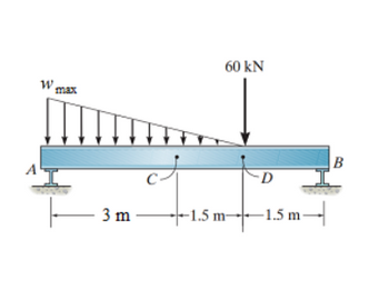
Assume point D is just to the left of the 60-kN force. Take wmax = 55 kN/m. Assume the support reactions at A and B are vertical
A) Determine the magnitude of the resultant internal normal force on the cross section at point D.
B)Determine the magnitude of the resultant internal shear force on the cross section at point D.

Transcribed Image Text:W max
3 m
60 KN
4152
-1.5 m-
D
-1.5 m-
B
Expert Solution
This question has been solved!
Explore an expertly crafted, step-by-step solution for a thorough understanding of key concepts.
This is a popular solution
Trending nowThis is a popular solution!
Step by stepSolved in 4 steps with 3 images

Knowledge Booster
Learn more about
Need a deep-dive on the concept behind this application? Look no further. Learn more about this topic, mechanical-engineering and related others by exploring similar questions and additional content below.Similar questions
- Hi, I am pretty confident with my answers for parts 1 2 3 and 4 but I was just wondering if someone could help me with part 5 thanksarrow_forwardQ.4) Determine the tensions in the three cables supporting a weight of 180 N as shown in figure below. Draw the necessary free-body diagram. 6 m 4 m 5 m i 5 m 8 m 8 m - yarrow_forward2. The figure shows a cantilevered beam, subjected to a uniformly distributed (rectangular) 40 N/m force along the section DE, a 50 N point force at point C, and a 200 N·m couple moment. a. Write the shear-force and bending-moment equations as a function of distance, x, measured from the leftmost point, A, for the entire beam. b. Using your shear-force and bending-moment equations, calculate the shear force and bending moment at x = 2 m and x = = 5 m. 200 N·m 50 N 40 N/m 1.m C D 2.5 m 1m 2.5 m E B 2 marrow_forward
- Cantilever beam has fixed support at the point A as shown in Fig. 4. Determine the component of the support reaction at that point (A). 6 kN }30° 30° 1.5 m 4 kN 1.5 m -1.5 m- Fig. 4arrow_forwardQ2. In the extruded profile shown in the figure, the maximum allowable stress in tension is 120 MPa and the maximum allowable stress in compression is 150 MPa. Find the maximum bending moment that can be applied to this profile. 20mm 40mm 20 mm 54mm yc 40 mm A= bh h %3D C. Rectangular area A = %3D Triangular areaarrow_forwardIn the figure shown, the aluminum strut has a cross-sectional area in the form of a cross. If it is subjected to the moment M= 8 kN.m: 1) determine the bending stress acting at points A and B, 2) show the results acting on a stress distribution diagram.arrow_forward
- F -1.5 m -1.5 m |A 1 m M 45° Determine the support reactions on the member in Fig. The collar at A is fixed to the member and can slide vertically along the vertical shaft. If F=856 N and M=590 N-m Find the Moment at point A, include the rotation in your answer.arrow_forwardQ4) A solid plastic ball of density 6.00 x 10² kg/m and radius 2.00 cm is attached by a lightweight string to the bottom of an aquarium filled with fresh water. What is the tension in the string? +y ball all 9 stringarrow_forwardA) Determine the moment in the beam as a function of x for 4ft<x<10ft B) Determine the shear in the beam as a function of x for 10ft<x<14ft C) Determine the moment in the beam as a function of x for 10ft<x<14ftarrow_forward
- The bent rod is supported by a ball-and-socket joint at B and the cables attached to points A and C as shown in the figure. The cable at C is in z-direction. The rod is subjected to two forces, F applied at C and P applied at D. Force P is along line AD. Determine the tensions in the two cables, the magnitude of force P, and the components of the support reaction at B. 100 F = {-20i+30j} N 400 300 Dimensions in mmarrow_forwardQ.1) The beam ABC is supported by a cable at C and is subjected to two forces of 30 kN and 40 kN as shown in the figure. Determine the maximum tension on the cable and reaction forces at point A. N as shown in the figure. Neglect the thickness of the beam. A 30 kN 45° B 40 KN C 4 m D 5 marrow_forwardHOW TO SOLVE THIS QUESTION USING CROSS PRODUCTarrow_forward
arrow_back_ios
SEE MORE QUESTIONS
arrow_forward_ios
Recommended textbooks for you
 Elements Of ElectromagneticsMechanical EngineeringISBN:9780190698614Author:Sadiku, Matthew N. O.Publisher:Oxford University Press
 Mechanics of Materials (10th Edition)Mechanical EngineeringISBN:9780134319650Author:Russell C. HibbelerPublisher:PEARSON
 Thermodynamics: An Engineering ApproachMechanical EngineeringISBN:9781259822674Author:Yunus A. Cengel Dr., Michael A. BolesPublisher:McGraw-Hill Education
 Control Systems EngineeringMechanical EngineeringISBN:9781118170519Author:Norman S. NisePublisher:WILEY
 Mechanics of Materials (MindTap Course List)Mechanical EngineeringISBN:9781337093347Author:Barry J. Goodno, James M. GerePublisher:Cengage Learning
 Engineering Mechanics: StaticsMechanical EngineeringISBN:9781118807330Author:James L. Meriam, L. G. Kraige, J. N. BoltonPublisher:WILEY

Elements Of Electromagnetics
Mechanical Engineering
ISBN:9780190698614
Author:Sadiku, Matthew N. O.
Publisher:Oxford University Press

Mechanics of Materials (10th Edition)
Mechanical Engineering
ISBN:9780134319650
Author:Russell C. Hibbeler
Publisher:PEARSON

Thermodynamics: An Engineering Approach
Mechanical Engineering
ISBN:9781259822674
Author:Yunus A. Cengel Dr., Michael A. Boles
Publisher:McGraw-Hill Education

Control Systems Engineering
Mechanical Engineering
ISBN:9781118170519
Author:Norman S. Nise
Publisher:WILEY

Mechanics of Materials (MindTap Course List)
Mechanical Engineering
ISBN:9781337093347
Author:Barry J. Goodno, James M. Gere
Publisher:Cengage Learning

Engineering Mechanics: Statics
Mechanical Engineering
ISBN:9781118807330
Author:James L. Meriam, L. G. Kraige, J. N. Bolton
Publisher:WILEY