The piston in an engine is attached to a connecting rod AB, which in turn is connected to a crank arm BC (see figure). The piston slides without friction in a cylinder and is subjected to a force P (assumed to be constant) while moving to the right in the Figure. The connecting rod. with diameter d and length L, is attached at both ends by pins. The crank arm rotates about the axle at C with the pin at B moving in a circle of radius R. The axle at C , which is supported by bearings, exerts a resisting moment M against the crank arm. (a) Obtain a formula for the maximum permissible force P a l l o w . based upon an allowable compressive stress a c in the connecting rod. (b) Calculate the Force P a l l o w for the following data:
The piston in an engine is attached to a connecting rod AB, which in turn is connected to a crank arm BC (see figure). The piston slides without friction in a cylinder and is subjected to a force P (assumed to be constant) while moving to the right in the Figure. The connecting rod. with diameter d and length L, is attached at both ends by pins. The crank arm rotates about the axle at C with the pin at B moving in a circle of radius R. The axle at C , which is supported by bearings, exerts a resisting moment M against the crank arm. (a) Obtain a formula for the maximum permissible force P a l l o w . based upon an allowable compressive stress a c in the connecting rod. (b) Calculate the Force P a l l o w for the following data:
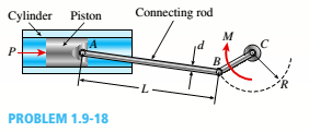
The piston in an engine is attached to a connecting rod AB, which in turn is connected to a crank arm BC (see figure). The piston slides without friction in a cylinder and is subjected to a force P (assumed to be constant) while moving to the right in the Figure. The connecting rod. with diameter d and length L, is attached at both ends by pins. The crank arm rotates about the axle at C with the pin at B moving in a circle of radius R. The axle at C, which is supported by bearings, exerts a resisting moment M against the crank arm.
(a) Obtain a formula for the maximum permissible force Pallow. based upon an allowable compressive stress acin the connecting rod.
(b) Calculate the Force Pallowfor the following data:
4- With the mechanism in the figure, the board at the E end will be compressed. Accordingly, the vertical P arm applied Vertical compression at end E in response to force calculate the force
P=(26)N, L1=(102)mm, L2 = (56)mm,a=b=(10)mm
For two existing torques, what third force at a given distance from the pivot will balance them?
Imagine a meter stick set up as in the figure. It hangs from a central bracket, and two hanging masses can hang from it from each of their brackets. At a third location, a force probe can either pull up or pull down on the stick, depending on what is needed to balance the stick.
The mass of the meter stick is 120 g.
sketch the situation (drawing r1, r2, r3, F1, F2, and F3) and determine the magnitude (value) and direction (+ or -) of each torque. Don't include the mass of a bracket that would hold the hanging mass in place; assume the mass listed is the entire mass hanging at that point.
For each trial, use the principle of equilibrium (where the sum of torques is zero) to calculate the third, unknown force acting at x3
A stationary bicycle wheel of radius 0.7 m is mounted in the vertical plane (see figure below). The axle is held up by supports that are not shown, and the wheel is free to rotate on the nearly frictionless axle. The wheel has mass 4.3 kg, all concentrated in the rim (the spokes have negligible mass). A lump of clay with mass 0.5 kg falls and sticks to the outer edge of the wheel at the location shown. Just before the impact the clay has speed 8 m/s, and the wheel is rotating clockwise with angular speed 0.27 rad/s. Assume +x is to the right, +y is upward, and +z is out of the page. Assume the line connecting the center to the point of impact is at an angle of 45° from the horizontal.Just after the impact, what is the angular velocity (magnitude and direction) of the wheel?
Chapter 1 Solutions
Bundle: Mechanics Of Materials, Loose-leaf Version, 9th + Mindtap Engineering, 1 Term (6 Months) Printed Access Card
Need a deep-dive on the concept behind this application? Look no further. Learn more about this topic, mechanical-engineering and related others by exploring similar questions and additional content below.
Mechanical SPRING DESIGN Strategy and Restrictions in Under 15 Minutes!; Author: Less Boring Lectures;https://www.youtube.com/watch?v=dsWQrzfQt3s;License: Standard Youtube License


 Mechanics of Materials (MindTap Course List)Mechanical EngineeringISBN:9781337093347Author:Barry J. Goodno, James M. GerePublisher:Cengage Learning