.15 A hitch-mounted bicycle rack is designed to carry up to four 30-lb bikes mounted on and strapped to two arms Gil (sec bike loads in the figure part a) The rack is attached to the vehicle at A and is assumed to be like a cant silkier beam A BCDGII (figure part b) The light of fixed segment AB is U = 10 lb. centered 9 in. from A (see figure part b) and the rest of the rack highs W2 = 40 lb. centered 19 in. from A. Segment ABCDG is a steel tube o(2 X 2 in. with a thickness I = 118 in. Segment BCDGII pivots about a bolt at B with a diameter d1 = 0.25 in. to allow access to the rear of the vehicle without removing the hitch rack. When in use, the rack is secured in an upright posit ion by a pin C(diameter o( pin d, = 5116 in.) (see phoo and figure part C). The of returning effect of the bikes on the rack is resisted by a force couple F h at BC. (a) Find the support reactions at A for the fully loaded rack. (b) Find forces in the bolt at B and the pin at C. (c) Find average shear stresses in both the bolt at Band the pin at C. (d) Find average bearing stresses o, in the bolt at B and the pin at C.
.15 A hitch-mounted bicycle rack is designed to carry up to four 30-lb bikes mounted on and strapped to two arms Gil (sec bike loads in the figure part a) The rack is attached to the vehicle at A and is assumed to be like a cant silkier beam A BCDGII (figure part b) The light of fixed segment AB is U = 10 lb. centered 9 in. from A (see figure part b) and the rest of the rack highs W2 = 40 lb. centered 19 in. from A. Segment ABCDG is a steel tube o(2 X 2 in. with a thickness I = 118 in. Segment BCDGII pivots about a bolt at B with a diameter d1 = 0.25 in. to allow access to the rear of the vehicle without removing the hitch rack. When in use, the rack is secured in an upright posit ion by a pin C(diameter o( pin d, = 5116 in.) (see phoo and figure part C). The of returning effect of the bikes on the rack is resisted by a force couple F h at BC. (a) Find the support reactions at A for the fully loaded rack. (b) Find forces in the bolt at B and the pin at C. (c) Find average shear stresses in both the bolt at Band the pin at C. (d) Find average bearing stresses o, in the bolt at B and the pin at C.
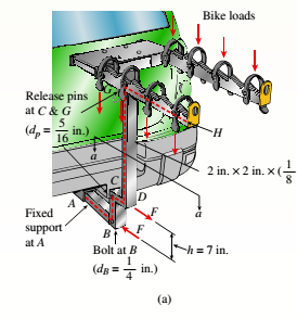
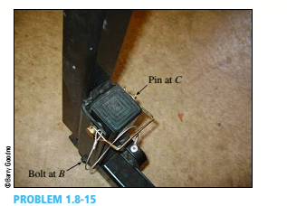
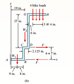
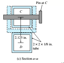
.15 A hitch-mounted bicycle rack is designed to carry up to four 30-lb bikes mounted on and strapped to two arms Gil (sec bike loads in the figure part a) The rack is attached to the vehicle at A and is assumed to be like a cant silkier beam A BCDGII (figure part b) The light of fixed segment AB is U = 10 lb. centered 9 in. from A (see figure part b) and the rest of the rack highs W2 = 40 lb. centered 19 in. from A. Segment ABCDG is a steel tube o(2 X 2 in. with a thickness I = 118 in. Segment BCDGII pivots about a bolt at B with a diameter d1 = 0.25 in. to allow access to the rear of the vehicle without removing the hitch rack. When in use, the rack is secured in an upright posit ion by a pin C(diameter o( pin d, = 5116 in.) (see phoo and figure part C). The of returning effect of the bikes on the rack is resisted by a force couple F h at BC.
(a) Find the support reactions at A for the fully loaded rack.
(b) Find forces in the bolt at B and the pin at C.
(c) Find average shear stresses in both the bolt at Band the pin at C. (d) Find average bearing stresses o, in the bolt at B and the pin at C.
A. The frame shown in Figure I is hinged to rigid supports at A and E.
Find the values of:
1. Force components of Hinge A
2. Force components of Hinge B
3. Force in Member BC
4. Force in Member BD
크
트
A
5'
3'
P = 600 15
FIGURE 1
DA
3'
3'
B
I need help please
Two gondolas on a ski lift are locked in the position shown in the figure while repairs are being made elsewhere. The distance between support towers is L = 100 ft. The length of each cable segment under gondola weights WB = 450 lb and WC = 650 lb are DAB = 12 ft, DBC = 70 ft, and DCD = 20 ft. The cable sag at B is ΔB = 3.9 ft and that at C(ΔC) is 7.1 ft. The effective cross-sectional area of the cable is Ae = 0.12 in2.(a) Find the tension force in each cable segment; neglect the mass of the cable.(b) Find the average stress (s) in each cable segment.
A rectangular sign on a store has a mass of 100.0 kg, with the center of mass at the center of the rectangle. Leaning against the wall at point C can be treated as a ball and socket joint. At corner D support is provided only in the y direction. Calculate the voltages T1 and T2 in the support cables; the total force supported at C; and the lateral force R supported at D
(need free body diagram)
Need a deep-dive on the concept behind this application? Look no further. Learn more about this topic, mechanical-engineering and related others by exploring similar questions and additional content below.


 Mechanics of Materials (MindTap Course List)Mechanical EngineeringISBN:9781337093347Author:Barry J. Goodno, James M. GerePublisher:Cengage Learning