Concept explainers
Videos
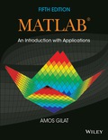
In the triangle shown a = 5 in., b = 7 in., and
- Calculate the length of c by substituting the variables in the Law of Cosines.
(Law of Cosines: c2= a2+ b2- 2abcos
Want to see the full answer?
Check out a sample textbook solution
Chapter 1 Solutions
EBK MATLAB: AN INTRODUCTION WITH APPLIC


- Calculate the steady state currents flowing through inductors L₁ and L₂ and the steady state voltage across capacitor C in the circuit L₁ mm Vs = 20 V L₁ = 4 mH R₁ = 1 A R₂ = 3 L₂= 7 mH C = 6 4F shown below: Ri wwwww HH Carrow_forward-Prove that in Maxwell bridge can be used to measure inductanceby either with a variable Comparison Standard self-inductance or with Standard variable capacitance Ru= d R₂ R3 R. Lu= R₂R₂ C R₂ A R3 Luarrow_forwardThe circuit shown in figure EM1-1 shows an AC voltage source VAC connected in series with a load that has • resistance R=280 Ohms, inductance L=1.1mH, and • capacitance C=4.7mF. Calculate values of, and select the apporpriate answer from the list from the list below for • the frequency, fres (in Hz) of the AC source that results in resonance in the load and the impedance, Zres (in Ohms) of the load at this frequency. ● Resonant Frequency, fres= ✓ Hz Impedance of the Load at Resonance, Zres= R 280 Ω ✓ Ohms V. AC L 4.7 mF 1.1 mH Figure EM1-1 Downloadable imagearrow_forward
- The picture shows three LC circuits, two of them with capacitors of capacitance C and the three with coils of inductance L, the three circuits are coupled by means of two capacitors Cc capacitors.L inductance coils, the three circuits are coupled by means of two capacitors of capacitance Cc. The currentscirculating through each mesh are those indicated in the figure: I1, I2 and I3. Using Kirchhoff's law for voltagesand taking into account the definition of current I = -dQ/dt, find the system of coupled equations for the systemand then find the angular normal frequencies of the system.arrow_forwardin V1 R2 100k SINE(0 10 100) R1 100k D1 D V2 0 out D D2 V3 0 DC offset[V]: 0 Amplitude[V]: 10 Freq[Hz]: 100 T delay[s]: Theta[1/s]: Phi[deg]: Ncycles: anter 2019-2220 Figure 3-5 Clipper Circuit for LTSPICE Simulation C4. To specify the type of simulation, select "Simulate>>Edit Simulation Cmd" from the menu. Choose "Transient" and enter 30m for Stop time, 0 for Time to start saving data, and 1m for Maximum Timestep. Click OK. C5. Click Run to start the analysis. C6. Place two voltage probes (voltage probes appear when placed on a wire during simulation), one at the input side (at the top of V1) and another at the output side (at the top of D2) of the circuit. What difference do you observe between the input and the output waveforms?arrow_forwardgoogle.com/forms/d/e/1FAlpQLScF2Wzu92iVI-tEM2nxdhqXrGdR460G4QCTxaUZZeC678PqTg/formResponse مطلوب /06 *:The potential at point P due to Q1 and Q2 is Q, = 1x10-12C 0.5 m 0.5 m Qz = 1x10-12C %3D 50 cm 0.01797 V Ov O -0.01271 V O 0.01271 V O Insert PIC F10 F11 F12 F6 F7 FB Backspace 9 € P Enter Harrow_forward
- Answer/solve the following problems. 1. Convert the following currents to polar form : a) 6 – i 8, b) – 6 + ¡8 , c) – ¡5.arrow_forwardQUESTION 3 An inductor, a capacitor, and a resistor are connected in series with a function generator. The inductor drops 5V RMS, the capacitor drops 20V RMS, and the resistor drops 2V RMS. Find the magnitude of the total voltage. O 27V RMS O 15V RMS O 38V RMS O 9V RMSarrow_forwardExplain the following 1. Diffrence between DC and AC Electricity. 2. how to convert rectangular form to polar form and polar form to rectangular form. 3. why need to improve a power factorarrow_forward
- Figure 2 shows three "LC" circuits, two of them with capacitors of capacitance "C" and the three with inductance coils "L", the three circuits are coupled by means of two capacitors "Cc" capacitors. inductance "L", the three circuits are coupled by means of two capacitors of capacitance "Cc". The currents circulating through each mesh are those indicated in the figure: "I1", "I2" and "I3". Using Kirchhoff's law for voltages and taking into account the definition of current I = -dQ/dt, find the system of coupled equations of the system and then find the angular normal frequencies of the system.arrow_forwardEngineering Electromagnetics: how did my textbook get this apporximation for gamma and alpha? I don't understand the derivation, it says to use the Taylor Series and I did.arrow_forwardH.W 2 An AC circuit includes two sections AB and BC in series. The section AB consists of two branches in parallel. The first of these is formed of resistance of 60 2 in series with a capacitor of 50 mF, while the second consists of a resistance of 60 2 having an inductance of 250 mH. The section BC consists of a resistance of 100 N having an inductance of 300 mH. The frequency of the current is 50 Hz. The voltage across section AB is 500 V. What is the voltage across the section BC?arrow_forward
 Introductory Circuit Analysis (13th Edition)Electrical EngineeringISBN:9780133923605Author:Robert L. BoylestadPublisher:PEARSON
 Delmar's Standard Textbook Of ElectricityElectrical EngineeringISBN:9781337900348Author:Stephen L. HermanPublisher:Cengage Learning
 Programmable Logic ControllersElectrical EngineeringISBN:9780073373843Author:Frank D. PetruzellaPublisher:McGraw-Hill Education
 Fundamentals of Electric CircuitsElectrical EngineeringISBN:9780078028229Author:Charles K Alexander, Matthew SadikuPublisher:McGraw-Hill Education
 Electric Circuits. (11th Edition)Electrical EngineeringISBN:9780134746968Author:James W. Nilsson, Susan RiedelPublisher:PEARSON
 Engineering ElectromagneticsElectrical EngineeringISBN:9780078028151Author:Hayt, William H. (william Hart), Jr, BUCK, John A.Publisher:Mcgraw-hill Education,