
Videos
Use KCL to find the values of
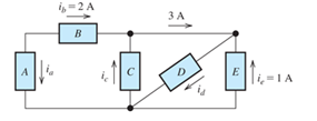
Figure P1.37

Learn your wayIncludes step-by-step video

Chapter 1 Solutions
Mastering Engineering with Pearson eText -- Standalone Access Card -- for Electrical Engineering: Principles & Applications
Additional Engineering Textbook Solutions
Fundamentals of Applied Electromagnetics (7th Edition)
Introductory Circuit Analysis (13th Edition)
Starting Out with Python (3rd Edition)
Materials for Civil and Construction Engineers (4th Edition)
Digital Fundamentals (11th Edition)
Starting Out with C++ from Control Structures to Objects (9th Edition)


- Consider the circuit shown in Figure P1.66. a. Which elements are in series?b. Which elements are in parallel?c. Apply Ohm’s and Kirchhoff’s laws to solve for V x.arrow_forwardUse KCL to find the values of i a, i c, and i d for the circuit of Figure P1.37. Which elements are connected in series in this circuit?arrow_forwardThe circuit below(left) displays a schematic diagram of a battery. The voltage measured by U1 is called the terminal voltage given R1 = 1 ohm. In the circuit below(right), the terminal voltage of each of the battery-resistor combination is VT = 1.5 volts. Find the voltage across R1 & voltage of the battery.arrow_forward
- Consider the circuit shown in Figure P1.64. Use Ohm’s law, KVL, and KCL to find V x.arrow_forwardSolve for the other voltages shown in Figure P1.43 given that v a = 5 V, v b = 7 V, v f = -10 V and v h = 6 V.arrow_forwardConsider the circuit shown in Figure P1.36. a. Which elements are in series ? b. What is the relationship between i d and i c ? c. Given that i a = 3 A and i c = 1 A, determine the values of i b and i d.arrow_forward
- Figure 2.1 shows a simple circuit. Explain why using a DMM tomeasure the DC voltage across resistor R2 might lead to inaccurate results. Include in your answer how the value of R2 might affect the size of the error and provide some circuit diagrams and equations to showhow to calculate the error.arrow_forwardThe circuit below(left) displays a schematic diagram of a battery. The voltage measured by U1 is called the terminal voltage given R1 = 1 ohm. In the circuit below(right), the terminal voltage of each of the battery-resistor combination is VT = 1.5 volts. Find the voltage across R1 & voltage of the battery. Find the percentage of voltage loss of the battery due to the internal resistance R1.arrow_forwardFor the circuit shown in Figure P1.76, solve for i s. What types of sources are present in this circuit?arrow_forward
- Suppose the three branch currents in this circuit are I₁ = -3 A, I₂ = -18 A, and I3 = -15 A. The voltage drop across each circuit element is as given in the table below. From this information, determine, for each of these circuit elements, (i) whether an active or passive sign convention is being used for that element, (ii) whether that element is absorbing or producing a net (positive) amount of electrical power. In each answer box within the table below, type the correct choice from among the bold-faced words above. V₂ B A B A C D 1₁ A B 1₂ 1₂ + Circuit element Voltage drop Sign convention? Absorbing or producing net electrical power? -9 V -2 V C 9 V -11 V Darrow_forwardIn the figure the ideal batteries have emfs ɛ1 = 20.4 V, ɛ2 = 9.05 V, and ɛ3 = 5.40 V, and the resistances are each 2.40 Q. What are the (a) size and (b) direction (left or right) of current i,? (c) Does battery 1 supply or absorb energy, and (d) what is its power? (e) Does battery 2 supply or absorb energy, and (f) what is its power? (g) Does battery 3 supply or absorb energy, and (h) what is its power? (a) Number i Units (b) (c) (d) Number i Units (e) (f) Number i Units (g) (h) Number i Unitsarrow_forwardNotes on the verification of ohm's law by voltage method?arrow_forward
 Introductory Circuit Analysis (13th Edition)Electrical EngineeringISBN:9780133923605Author:Robert L. BoylestadPublisher:PEARSON
 Delmar's Standard Textbook Of ElectricityElectrical EngineeringISBN:9781337900348Author:Stephen L. HermanPublisher:Cengage Learning
 Programmable Logic ControllersElectrical EngineeringISBN:9780073373843Author:Frank D. PetruzellaPublisher:McGraw-Hill Education
 Fundamentals of Electric CircuitsElectrical EngineeringISBN:9780078028229Author:Charles K Alexander, Matthew SadikuPublisher:McGraw-Hill Education
 Electric Circuits. (11th Edition)Electrical EngineeringISBN:9780134746968Author:James W. Nilsson, Susan RiedelPublisher:PEARSON
 Engineering ElectromagneticsElectrical EngineeringISBN:9780078028151Author:Hayt, William H. (william Hart), Jr, BUCK, John A.Publisher:Mcgraw-hill Education,