
Concept explainers
Videos
Figure P1.27 shows an ammeter (AM) and voltmeter (VM) connected to measure the current and voltage, respectively, for circuit element A.When current actually enters the + terminal of the ammeter, the reading is positive, and when current leaves the + terminal, the reading is negative. If the actual voltage polarity is positive at the + terminal of the VM, the reading is positive; otherwise, it is negative. (Actually, for the connection shown, the ammeter reads the sum of the current in element A and the very small current taken by the voltmeter. For purposes of this problem, assume that the current taken by the voltmeter is negligible.) Find the power for element A and state whether energy is being delivered to element A or taken from it if
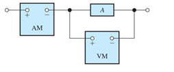
Figure P1.27
- the ammeter reading is +2 A and the voltmeter reading is +30 V;
Want to see the full answer?
Check out a sample textbook solution
Chapter 1 Solutions
Pearson eText for Electrical Engineering: Principles & Applications -- Instant Access (Pearson+)
Additional Engineering Textbook Solutions
Principles Of Electric Circuits
Programmable Logic Controllers
ELECTRICITY FOR TRADES (LOOSELEAF)
Principles and Applications of Electrical Engineering
Electric machinery fundamentals
Electric Motors and Control Systems


- A PMMC instrument has internal resistance of 0.9 kN and gives full scale deflection for 53 mA. The required resistance value of multiplier resistors for employing the meter as a multi range voltmeter for voltage range 77 V will be ohms. O -211.69 O 144.38 O 85502.56 O 552.83arrow_forwarda) Write the expression for the voltage vC after the switch is closed b) Write the expression for the current iC after the switch is closed. Plot the results of parts (a) and (b).arrow_forwardThe semiconductors is a materials whose conductivity and resistivity is more than conductors and insulators true O Falsearrow_forward
- For the circuit shown in Figure P1.76, solve for i s. What types of sources are present in this circuit?arrow_forward5.) In a parallel circuit: A) Each branch of the circuit must have the same potential difference B) Each branch of the circuit can have a different current C) Both of the above D) None of the above 5) 6.) A semiconductor is a material that: A) Has a resistance between a true conductor and a true insulator 6) B) Behaves like a conductor under certain conditions and an insulator at other times C) Both of the above D) None of the abovearrow_forwarda series circuit contains a resistor and an inductor as shown in figure 1.3.14. determine a differential equation for the current i (t) if the resistance is R, the inductance is L, and the impressed voltage is E(t)arrow_forward
- Identify elements that are in parallel a. in Figure P1.37, b. in Figure P1.43, c. in Figure P1.44.arrow_forwardA PMMC type meter has a full scale deflection of 10 mA. The resistance of the coil is 30 ohm. Then (1) shunt value for an Ameter of 50 A range and (2) Find the value of series resistance required for the range up to 500 V.arrow_forwardPart1: Resistors connected in series to each other The circuit shown below was generated on MapleSIM 2019 Voltmeter 1 Voltmeter 2 Voltmeter 3 Ammeter 2 Ammeter 1 RI=25Ohms R2=500hms R3=750hms Ammeter 3 6V The response of this circuit, i.e., the values of the probes measuring voltages and currents was simulated for a total time of 10s. The simulated data is shown below * Analysis Window: Simulation Results E Probe Pluts - Simulation Results V Stored Results Ammeter 3i Ammeter li Ammeter 21 0.050 0 050- 0 050- 0.045 0.045 0.045- Vanables 0 040 O 040 0 040 Find 0.035- 0.035 0.035- Main No Stored Resut Selected 0030- 0030 0 030 16 41 16 2 6 7 8 Hot Windovs Senes Datas. Veltmeter 1v Valtmeter 2y Volmeter 3.v 4.5- 65 ala Probe Plots E Ammeter J E Aeter 2a B Ammotor 3.1 E Voltmeter 1v Av voltmeter Z.v 05 3.5 Vettreeter 3.N 1.5 25 -05- -0.5 14- 21 1.5 12 10 12 10arrow_forward
- Electrical engineering assignment part 2.3arrow_forwarda. A sine voltage trace displayed on a screen is shown in figure2. The x axis is 1unit=50 ms and y axis, 1 unit=2 V; determine the frequency of the sine wave and plot the waveform if the same is applied to the input of a half wave rectifier. Figure2arrow_forwardA sample of wire (1 mm in diameter by 1 m in diameter) length) of an aluminum alloy (containing 1.2% Mn) is placed in an electrical circuit, as shown in the figure next to. A voltage drop of 432 mV is measured at wire length when it carries a 10 A current. Calculate the conductivity of this alloy.arrow_forward
 Introductory Circuit Analysis (13th Edition)Electrical EngineeringISBN:9780133923605Author:Robert L. BoylestadPublisher:PEARSON
 Delmar's Standard Textbook Of ElectricityElectrical EngineeringISBN:9781337900348Author:Stephen L. HermanPublisher:Cengage Learning
 Programmable Logic ControllersElectrical EngineeringISBN:9780073373843Author:Frank D. PetruzellaPublisher:McGraw-Hill Education
 Fundamentals of Electric CircuitsElectrical EngineeringISBN:9780078028229Author:Charles K Alexander, Matthew SadikuPublisher:McGraw-Hill Education
 Electric Circuits. (11th Edition)Electrical EngineeringISBN:9780134746968Author:James W. Nilsson, Susan RiedelPublisher:PEARSON
 Engineering ElectromagneticsElectrical EngineeringISBN:9780078028151Author:Hayt, William H. (william Hart), Jr, BUCK, John A.Publisher:Mcgraw-hill Education,