
ANALYSIS+DESIGN OF LINEAR CIRCUITS(LL)
8th Edition
ISBN: 9781119235385
Author: Thomas
Publisher: WILEY
expand_more
expand_more
format_list_bulleted
Videos
Textbook Question
Chapter 1, Problem 1.22P
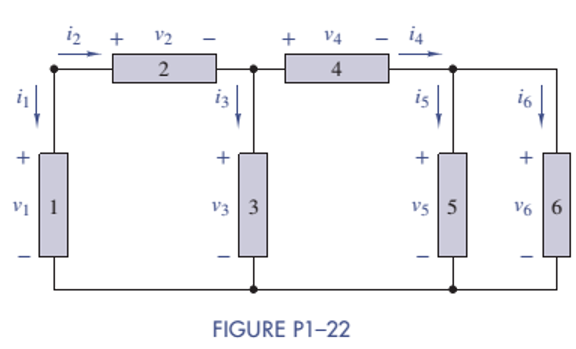
Figure P1-22 shows an electric circuit with a voltage and a current variable assigned to each of the six devices. The device voltages and currents are observed to be as follows: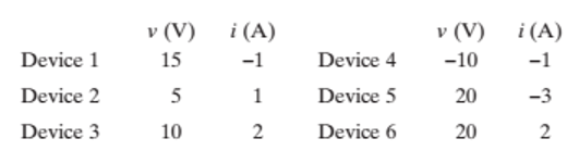
Find the power associated with each device and state whether the device is absorbing or delivering power. Use the power balance to check your work.
Expert Solution & Answer
Want to see the full answer?
Check out a sample textbook solution
Students have asked these similar questions
What are the factors that affects or influence the electrical properties of a material? c) Two of you have been given two instruments with the units in ohms, your colleague measures the resistivity of the material whiles you measure the resistance. Your supervisor comes around and ask you to comment both measurements, what would you tell him?
SOLVE FOR THE VALUE OF RESISTANCE
Consider the circuit shown in Figure P1.62. Find the current iR flowing through the resistor. Find the power for each element in the circuit. Which elements are absorbing power?
Chapter 1 Solutions
ANALYSIS+DESIGN OF LINEAR CIRCUITS(LL)
Ch. 1 - Given an electrical quantity described in terms of...Ch. 1 - Express the following quantities to the nearest...Ch. 1 - An ampere-hour (Ah) meter measures the time...Ch. 1 - Electric power companies measure energy...Ch. 1 - Fill in the blanks in the following statements. To...Ch. 1 - Which of the two entries is larger? 1000...Ch. 1 - A wire carries a constant current of 30A. How many...Ch. 1 - The net positive charge flowing through a device...Ch. 1 - Figure P1-9 shows a plot of the net positive...Ch. 1 - The net negative charge flowing through a device...
Ch. 1 - A cell phone charger outputs 9.6 V and is...Ch. 1 - For 0t5s, the current through a device is...Ch. 1 - The charge flowing through a device is...Ch. 1 - The 12-V automobile battery in Figure P1-14 has an...Ch. 1 - The current through a device is zero for t0 and is...Ch. 1 - A string of holiday lights is protected by a 12A...Ch. 1 - When illuminated the relationship for a photocell...Ch. 1 - A new 6-V alkaline lantern battery delivers...Ch. 1 - The maximum current allowed by a device's power...Ch. 1 - Traffic lights are being converted from...Ch. 1 - Two electrical devices are connected as shown in...Ch. 1 - Figure P1-22 shows an electric circuit with a...Ch. 1 - Figure P1-22 shows an electric circuit with a...Ch. 1 - In Figure P1-24 the voltage v2 is 10 V and v4 is 5...Ch. 1 - For t0, the voltage across and power absorbed by a...Ch. 1 - Repeat Problem 1-22 using MATLAB to perform the...Ch. 1 - Using the passive sign convention, the voltage...Ch. 1 - Power Ratio (PR) in dB A stereo amplifier takes...Ch. 1 - AC to DC Converter A manufacturer's data sheet for...Ch. 1 - Charge-Storage Device A capacitor is a...Ch. 1 - Compute Data Sheet A manufacturer's data sheet for...Ch. 1 - Light Source Comparison A Today people have three...
Additional Engineering Textbook Solutions
Find more solutions based on key concepts
The resistance and inductance of the circuit in Fig. 8.5 are 100 and 20 mH, respectively.
Find the value of C t...
Electric Circuits. (11th Edition)
Explain Faradays law and the function of Lenzs law.
Fundamentals of Applied Electromagnetics (7th Edition)
Using Kirchhoffs current law, determine the unknown currents for the networks in Fig. 6.91.
Introductory Circuit Analysis (13th Edition)
In the circuit shown in Fig. P 7.26, both switches operate together; that is, they either open or close at the ...
Electric Circuits (10th Edition)
The current through a 0.5F capacitor is shown in Figure P3.11. At t = 0, the voltage is zero Sketch the voltage...
Electrical Engineering: Principles & Applications (7th Edition)
Use source exchange to find Io in the network in Fig. P5.111.
Basic Engineering Circuit Analysis
Knowledge Booster


Learn more about
Need a deep-dive on the concept behind this application? Look no further. Learn more about this topic, electrical-engineering and related others by exploring similar questions and additional content below.Similar questions
- It is a Basics electrical subject. Please show the illustration and give the complete and step by step solution. Limit your decimal point into 3 decimal places if it nedded. Please answer number 4arrow_forwardA is measured in coulombs, B is measured in seconds, C is measured in volts, and D is measured in seconds. Give the power of this component at t2 = 7 sec. You must round your answer to the nearest thousandth and give your answer as an integer followed by the appropriate metric prefix and the letter that represents the units of power.arrow_forwardIt is a Basics electrical subject. Please show the illustration and give the complete and step by step solution. Limit your decimal point into 3 decimal places if it nedded.arrow_forward
- Figure P1.27 shows an ammeter (AM) and voltmeter (VM) connected to measure thecurrent and voltage, respectively, for circuit element A. When current actually enters the + terminalof the ammeter, the reading is positive, and when current leaves the + terminalreading is negative. If the actual voltage polarity is positive at the + terminal of the VM, thereading is positive; otherwise, it is negative. (Actually, for the connection shown, the ammeterreads the sum of the current in element A and the very small current taken by the voltmeter. Forpurposes of this problem, assume that the current taken by the voltmeter is negligible.) Find thepower for element A and state whether energy is being delivered to element A or taken from it if a. the ammeter reading is +2 A and the voltmeter reading is +30 V.b. the ammeter reading is -2 A and the voltmeter reading is - 30 V.c. the ammeter reading is -2 A and the voltmeter reading is + 30 V.arrow_forwardPlease show all work and steps like eq1 and 2, etc. Thank youarrow_forwardSolve number 1. Plz show all work and tips to help for this practice problem. Thank youarrow_forward
- The voltages V1, V2, and V3 are measured with respect to the reference shown in the diagram. Find the value of the voltage V1 in volts. (Note the polarity of the voltages.)arrow_forwardSince R1=5619.38ohm, R2=1949.32ohm and Ri=Infinite in the circuit given in the figure, write the equivalent resistance in Ohms between the terminals A-B. When making your transactions, 2 digits will be taken after the dot.arrow_forwardConsider the circuit shown in Figure P1.63. Find the current i R flowing through the resistor. Find the power for each element in the circuit. Which elements are receiving power?arrow_forward
- Find the voltage across the 30-ohm resistor and the power supplied by the 4-ampere current source.arrow_forwardThe current and power for each of the interconnected elements inP1.32 is measured. The values are listed in Table P1.32. Identify the elements that absorb power.arrow_forwardState the Mathematical relationship between the sides of the power triangle.arrow_forward
arrow_back_ios
SEE MORE QUESTIONS
arrow_forward_ios
Recommended textbooks for you
 Introductory Circuit Analysis (13th Edition)Electrical EngineeringISBN:9780133923605Author:Robert L. BoylestadPublisher:PEARSON
 Delmar's Standard Textbook Of ElectricityElectrical EngineeringISBN:9781337900348Author:Stephen L. HermanPublisher:Cengage Learning
 Programmable Logic ControllersElectrical EngineeringISBN:9780073373843Author:Frank D. PetruzellaPublisher:McGraw-Hill Education
 Fundamentals of Electric CircuitsElectrical EngineeringISBN:9780078028229Author:Charles K Alexander, Matthew SadikuPublisher:McGraw-Hill Education
 Electric Circuits. (11th Edition)Electrical EngineeringISBN:9780134746968Author:James W. Nilsson, Susan RiedelPublisher:PEARSON
 Engineering ElectromagneticsElectrical EngineeringISBN:9780078028151Author:Hayt, William H. (william Hart), Jr, BUCK, John A.Publisher:Mcgraw-hill Education,
Introductory Circuit Analysis (13th Edition)
Electrical Engineering
ISBN:9780133923605
Author:Robert L. Boylestad
Publisher:PEARSON
Delmar's Standard Textbook Of Electricity
Electrical Engineering
ISBN:9781337900348
Author:Stephen L. Herman
Publisher:Cengage Learning
Programmable Logic Controllers
Electrical Engineering
ISBN:9780073373843
Author:Frank D. Petruzella
Publisher:McGraw-Hill Education
Fundamentals of Electric Circuits
Electrical Engineering
ISBN:9780078028229
Author:Charles K Alexander, Matthew Sadiku
Publisher:McGraw-Hill Education
Electric Circuits. (11th Edition)
Electrical Engineering
ISBN:9780134746968
Author:James W. Nilsson, Susan Riedel
Publisher:PEARSON
Engineering Electromagnetics
Electrical Engineering
ISBN:9780078028151
Author:Hayt, William H. (william Hart), Jr, BUCK, John A.
Publisher:Mcgraw-hill Education,
Lesson 2 - Source Transformations, Part 2 (Engineering Circuits); Author: Math and Science;https://www.youtube.com/watch?v=7gno74RhVGQ;License: Standard Youtube License