
Related questions
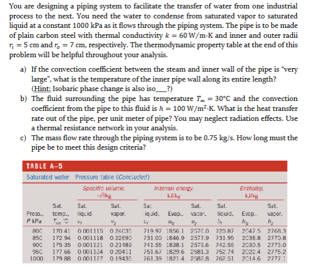
You are designing a piping system to facilitate the transfer of water from one industrial
process to the next. You need the water to condense from saturated vapor to saturated
liquid at a constant 1000 kPa as it flows through the piping system. The pipe is to be made
of plain carbon steel with thermal conductivity ? = 60 W m-K⁄ and inner and outer radii
?? = 5 cm and ?? = 7 cm, respectively. The
problem will be helpful throughout your analysis.
a) If the convection coefficient between the steam and inner wall of the pipe is “very
large”, what is the temperature of the inner pipe wall along its entire length?
(Hint: Isobaric phase change is also iso___?)
b) The fluid surrounding the pipe has temperature ?∞ = 30°C and the convection
coefficient from the pipe to this fluid is ℎ = 100 W/m2⋅K. What is the heat transfer
rate out of the pipe, per unit meter of pipe? You may neglect radiation effects. Use
a thermal resistance network in your analysis.
c) The mass flow rate through the piping system is to be 0.75 kg/s. How long must the
pipe be to meet this design criteria?


Trending nowThis is a popular solution!

Step by stepSolved in 4 steps with 17 images


- Flow Characteritistics( Enternce Effect) Why was there some diagrement between the actual Pitot tube velocity profile and the power law velocity profile?arrow_forwardThe clean U for an exchanger is 770 BTU/(hr 0 F ft2). Its tube area is 550 ft2. After operating for several months, it is heating water from 40 0F to 150 0F at a flow rate of 200 GPM with a heating fluid on the shell entering at 300 0F and exiting at 170 0 F. Has the overall U decreased significantly? how many 1.0 inch diameter, 20 ft long tubes would it take to equal the 550 ft2 area?arrow_forward4. The following heat exchanger uses 10 kg/s of hot air to heat and boil liquid water into saturated steam at 500 kPa. (a) Find the steam flow (kg/s) (b) Determine whether the process is allowed by the second law (Answer: It is not!) (c) On the surface, the process looks OK as Tair>Twater at both the inlet and outlet. You should be able to see the problem if you sketch the air and the water temperature profiles as you move left to right through the exchanger. (Hints: The air will be essentially a straight line, while the water will not. For the water, think about what happens when it is changing phase.) This is called a pinch point violation, and it is a very important design consideration in advanced combined cycle systems and in nuclear power plants. Air 100 kPa 160°C 10 kg/s Saturated Vapor 500 kPa Air: 160°C Steam: 151.8°C Q Air 100 kPa 30°C Liquid Water 500 kPa, 20°C Air: 30°C Water: 20°Carrow_forward
- A liquid (SG = 0.8 and μ = 5 CP = 0.00336 lbm/ft s) from a solvent recovery plant is being pumped from a vessel into a reactor. The flow rate to the rector is 100 GPM (0.2228 ft³/s,) and the line, schedule 40-carbon steel (a = 0.0018 in). The pressure in the vessel is 15 psig and the reactor is pressurized to 65 psig. The flow into the reactor is 25 ft below the level in the vessel as shown in the drawing. The centrifugal pump is located 5 ft below the level in the vessel. The piping consists of the following: Suction line 10 ft of 2.5" Pipe Gate valves 90 degree elbows Check valves 2" sch 40 pipe 2.5" Sch 40 pipe Gate valve Check Valve 90° elbows 2 2 1 ID = 2.067" ID=2.47" K = 8 ft K= 100 fr K = 30 ff Discharge line 325 ft of 2" 2 5 none Acs=0.0233 ft² Acs = 0.0332 ft² a. Determine the velocity in the 2.5" and 2" lines (ft /s). b. Determine the losses due to friction in both the suction and discharge lines (ft lbi/lbm). c. Estimate the amount of total dynamic head required of the pump…arrow_forward2.arrow_forwardA shell-and-tube heat exchanger is used to cool compressed liquid methanol from 176 °F to 104 °F. The methanol flows on the shell side of the exchanger. The coolant is water that rises in temperature from 50 °F to 86 °F and flows within the tubes at a rate of 68.9 kg s1. Finding the appropriate thermophysical data and applying the proper equations, you are required to do the following: (a) Calculate i) methanol mass flow rate in the exchanger, ii) methanol volumetric flowrate at the inlet of the exchanger. (b) i) For the counter-current flow of the fluids calculate the log temperature difference, ii) explain the purpose of calculating this difference, iii) explain, quantitatively, why is the counter-current flow in heat exchangers preferred to co-current flow. meanarrow_forward
- The clean U for an exchanger is 800 BTU/(hr 0 F ft2). Its tube area is 600 ft2. After operating for several months heating water from 50 0F to 160 0F at a flow rate of 210 GPM with a heating fluid on the shell entering at 290 0F and exiting at 160 0 F has the overall U decreased significantly?arrow_forwardIndustrial Pipes Are compression joints only used in small diameter pipelines, e.g. in compressed air systems for instrumentation?arrow_forwardSteam CERE KJ -Valve Control volume boundary Turbine Initially evacuated tank In case of emergencies, a turbine is connected to an active steam pipe line using a valve. When the valve is opened, steam from the pipe line, which is initially at 550°C and 10 MPa, flows through the turbine into a 0.64 m³ tank, which is initially evacuated. The valve is closed when the pressure inside the tank is 1.6 MPa and the temperature in the tank is 300°C. If the entire process is completed adiabatically, what is the amount of work generated from the turbine?arrow_forward
- Should the inlet and outlet pipes in a tank, pressure vessel, tooth and other equipment be positioned as far apart as possible from each other?arrow_forwardA straight-condensing 10,000 kW turbine has a guaranteed steam rate of 5.90 kg/kW.hr when exhausting at 5.0 kPa. Exhaust steam enters the condenser at 92% quality, and it is estimated that fouling will decrease the overall coefficient by 30% during operation. Cooling water is available at 18 ℃, and for design purposes, 1 ½ in OD 16 BWG Brass tubes (thickness = 0.065 in, k=62 BTU/hrftF°.) are specified with 9 C° rise in cooling water, which circulates at 5 ft/s. Inside and outside film coefficients are hi=960 and ho=1474 BTU/hrft2F°. Design a condenser for this turbine, considering tube and boundary resistance as flat surfaces and neglecting any crossflow factor. Determine the followinga) Effective overall coefficient of heat transferb) Volume flow rate of cooling waterc) Number of tubes for single passd) Length of tubesarrow_forward
- Elements Of ElectromagneticsMechanical EngineeringISBN:9780190698614Author:Sadiku, Matthew N. O.Publisher:Oxford University Press
 Mechanics of Materials (10th Edition)Mechanical EngineeringISBN:9780134319650Author:Russell C. HibbelerPublisher:PEARSON
 Thermodynamics: An Engineering ApproachMechanical EngineeringISBN:9781259822674Author:Yunus A. Cengel Dr., Michael A. BolesPublisher:McGraw-Hill Education
  Control Systems EngineeringMechanical EngineeringISBN:9781118170519Author:Norman S. NisePublisher:WILEY
 Mechanics of Materials (MindTap Course List)Mechanical EngineeringISBN:9781337093347Author:Barry J. Goodno, James M. GerePublisher:Cengage Learning
 Engineering Mechanics: StaticsMechanical EngineeringISBN:9781118807330Author:James L. Meriam, L. G. Kraige, J. N. BoltonPublisher:WILEY