Introductory Circuit Analysis (13th Edition)
13th Edition
ISBN: 9780133923605
Author: Robert L. Boylestad
Publisher: PEARSON
expand_more
expand_more
format_list_bulleted
Question

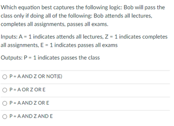
Transcribed Image Text:Which equation best captures the following logic: Bob will pass the
class only if doing all of the following: Bob attends all lectures,
completes all assignments, passes all exams.
Inputs: A = 1 indicates attends all lectures, Z = 1 indicates completes
all assignments, E = 1 indicates passes all exams
Outputs: P = 1 indicates passes the class
O P=AAND Z OR NOT(E)
O P=AORZ ORE
P = AAND Z OR E
O P=AAND Z AND E
Expert Solution
arrow_forward
Step 1
We need to select correct option for given statement .
Step by stepSolved in 2 steps

Knowledge Booster
Learn more about
Need a deep-dive on the concept behind this application? Look no further. Learn more about this topic, electrical-engineering and related others by exploring similar questions and additional content below.Similar questions
- I need the answer as soon as possiblearrow_forward30 For the circuit attached:Give the AND-OR expression as it is shown (No Spaces in your expression w'y+yz' not w'y + yz') (List from the top AND gate to the bottom AND gate)Draw a K-Map for it (Do not attach the K-Map) Give the minimum AND-OR expression for itarrow_forwardThe purpose of ohm's law experiment to verify the relation between I and P* True Falsearrow_forward
- Digital Logicarrow_forwardQ2) Design a combinational circuit which take 4bit input and it has 7 outputs to which connect with the 7-segment common cathode. Your circuit has to display any one of the following alphabet on 7-segment. 1010= A 1011= b 1100= C 1101= d 1110= E 1111= F Attach the truth table & K-map with proteus screen shot showing result. From the above choice choose any one alphabet to display.arrow_forwardWith the help of diagrams please..arrow_forward
- What are don’t care conditions for the function F=A´B´C´D+A´BC+AB´C if its simplification gives us F=A´C+B´C+A´B´? a)d=A´B´+A´D b)d=A´C´+A´D c)d=A´B´C+A´D d)d=A´B´C+A´B´D´ e)d=A´B´C+A´BD´arrow_forwardThe state transition diagram for the logic circuit shown is J O A=1 Q=0 A=0 Q=0 A=1 A=0 A=1 D CLK A=0 Q=1 A=1 Q=1 Q 2-1 MUX X1 I XO Y Select Alo (B) @ A=0 Q=0 A=1 Q=0 A=1 A=1 A=0 A=0 A=0 Q=1 A=1 Q=1arrow_forwardcan you please explain how did we solved it step by step ..arrow_forward
- Remember, binary subtraction is implemented by adding the 2's complement value of the subtrahend. In the following predictions, be sure to negate the subtrahends. Set #1 SUB Set #2 SUB A= 7 B= 2 A= B= S= Cout= Overflow Set #3: SUB A= B= 1 3 S= Cout= -8 4 Overflow A3 B3 S3 A₂ S3 A₁ B₂ B₁ B3 B₂ Ao Bo S₂ S₁ So A3 A₂ A₁ Ao B₁1 Bo S2 S₁ So S= Cout= Overflow Set #4 SUB A= -6 B= -5 S= Cout= Overflow A3 B3 A3 B3 A₂ S3 B₂ A₁ S3 S₂ S₁ So A₂ В1 Ao Bo B₂ В1 A₁ Ao Bo S₂ S₁ Soarrow_forward-VÁ VREF $₂ R Set/reset O- + Integrator Control logic 001 Clock + Comparator b1 b2 b3 bN The above figure is to be designed as a 7-bit A/D device. Suppose VREF = 7V and Clock time period 4us. What is the output digital output if v' = 5.6000V? A Counter How much time it would take to produce the output from the moment switch S2 is connected to -v ? A usarrow_forwardProblem 15 Given this circuit, what are the values at #1 , #2, and F1, for all possible values of the inputs. U2B OF1 U3A 5. 3. 7408 U1A 7432 7404 #1 #2arrow_forward
arrow_back_ios
SEE MORE QUESTIONS
arrow_forward_ios
Recommended textbooks for you
 Introductory Circuit Analysis (13th Edition)Electrical EngineeringISBN:9780133923605Author:Robert L. BoylestadPublisher:PEARSON
 Delmar's Standard Textbook Of ElectricityElectrical EngineeringISBN:9781337900348Author:Stephen L. HermanPublisher:Cengage Learning
 Programmable Logic ControllersElectrical EngineeringISBN:9780073373843Author:Frank D. PetruzellaPublisher:McGraw-Hill Education
 Fundamentals of Electric CircuitsElectrical EngineeringISBN:9780078028229Author:Charles K Alexander, Matthew SadikuPublisher:McGraw-Hill Education
 Electric Circuits. (11th Edition)Electrical EngineeringISBN:9780134746968Author:James W. Nilsson, Susan RiedelPublisher:PEARSON
 Engineering ElectromagneticsElectrical EngineeringISBN:9780078028151Author:Hayt, William H. (william Hart), Jr, BUCK, John A.Publisher:Mcgraw-hill Education,

Introductory Circuit Analysis (13th Edition)
Electrical Engineering
ISBN:9780133923605
Author:Robert L. Boylestad
Publisher:PEARSON

Delmar's Standard Textbook Of Electricity
Electrical Engineering
ISBN:9781337900348
Author:Stephen L. Herman
Publisher:Cengage Learning

Programmable Logic Controllers
Electrical Engineering
ISBN:9780073373843
Author:Frank D. Petruzella
Publisher:McGraw-Hill Education

Fundamentals of Electric Circuits
Electrical Engineering
ISBN:9780078028229
Author:Charles K Alexander, Matthew Sadiku
Publisher:McGraw-Hill Education

Electric Circuits. (11th Edition)
Electrical Engineering
ISBN:9780134746968
Author:James W. Nilsson, Susan Riedel
Publisher:PEARSON

Engineering Electromagnetics
Electrical Engineering
ISBN:9780078028151
Author:Hayt, William H. (william Hart), Jr, BUCK, John A.
Publisher:Mcgraw-hill Education,