Introductory Circuit Analysis (13th Edition)
13th Edition
ISBN: 9780133923605
Author: Robert L. Boylestad
Publisher: PEARSON
expand_more
expand_more
format_list_bulleted
Concept explainers
Question

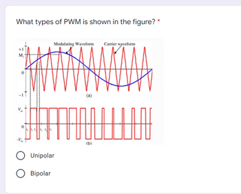
Transcribed Image Text:What types of PWM is shown in the figure? *
Modulating Waveform Carrier waveform
A
(b)
44444
F
-V
O Unipolar
O Bipolar
000
Expert Solution
This question has been solved!
Explore an expertly crafted, step-by-step solution for a thorough understanding of key concepts.
Step by stepSolved in 2 steps

Knowledge Booster
Learn more about
Need a deep-dive on the concept behind this application? Look no further. Learn more about this topic, electrical-engineering and related others by exploring similar questions and additional content below.Similar questions
- Full-wave 50 Hz sinusoidal controlled rectifier circuit with a peak voltage value of 100 and a source inductance of 8mH is feeding a highly inductive load of 8A. At a firing angle of 60 , the average value of the output voltage and power delivered are, respectively: Power Electronicsarrow_forwardAn unipolar PWM full bridge circuit has a Vr.rms of 125V at a duty cycle D1 of 0.7. What is Vd? What is Vo.rms?arrow_forwardThe input voltage (vin) of the following circuit is a sinusoidal signal with an amplitude of 2Vrms,consider a silicon diode.graph the output voltage ?? and the current across the resistor.arrow_forward
- A Capacitor filter is used at the output across the load to minimize the ripple factor of the output voltage. If R = 20 02 and the single- phase bridge rectifier is supplied from a 120V - 60 Hz sinusoidal source. Find the capacitor value in millifarads that will maintain the amount of the output ripples to less than 5% 艹 Ce = m₂ 0 mF RL%arrow_forwardFor the given circuit below, it operates on a peak-to-peak input voltage of 347.1 V, F = 60 Hz household supply through a step- down transformer with turns N1 = 10 and N2 = 1. Silicon diodes are used with a 1 Kiloohms load. Determine the output peak voltage (in volts). D1 D2 AC Input Vsec B (source) D3 D4 Load 24.30 15.96 12.40 O 18.75arrow_forwardGiven the following with Q = 0 as initial state, What do the Q and Q0 waveforms look like? SET RESET Qarrow_forward
- A step down converter is operated with a duty cycle of k = 0.75. The input voltage is Vs = 20V, and the load is: L = 5mH, R = 1502. The minimum inductor current is I₁ = 0.1A. The maximum inductor current is: Select one: a. 1.9 A b. None of these OC. 0.9 A O d. 1.1 A Oe. 2 Aarrow_forwardfind the average power consume by RL for both fullwave and halfwave rectifier circuit.arrow_forwardC'uk Converter Design A C'uk converter has an input of 12 V and is to have an output of - 24 V supplying a 60 W load. Select the duty ratio, the switching frequency, the inductor sizes such that the change in inductor currents is no more than 12 percent of the average inductor current, the output ripple voltage is no more than 1.5 percent, and the ripple voltage across C1 is no more than 3 percent.arrow_forward
- The circle is below(for D1-1N4148 is 1N4148 Diode). and also there have a table(. Note that the first 3 rows of measurement are obtained when the diode is reverse-biased) Vout_dc (V) VD (V) ID (μA) 0.51 -0.51 0.0 0.23 -0.20 0.0 0.10 -0.08 0.0 0.00 0.00 0.0 0.05 0.04 0.0 0.11 0.09 0.0 0.17 0.15 0.1 0.19 0.20 0.1 0.27 0.25 0.4 0.32 0.30 1.6 0.36 0.34 3.1 0.42 0.40 8.2 0.46 0.42 14.3 0.52 0.47 28.0 Questions: 1) plot the diode’s I-V characteristics on a linear scale (ID on the y-axis and VD on the x-axis) 2) [RP4] 3) [RP5]arrow_forwardPlease do D, E, and Farrow_forward
arrow_back_ios
arrow_forward_ios
Recommended textbooks for you
 Introductory Circuit Analysis (13th Edition)Electrical EngineeringISBN:9780133923605Author:Robert L. BoylestadPublisher:PEARSON
 Delmar's Standard Textbook Of ElectricityElectrical EngineeringISBN:9781337900348Author:Stephen L. HermanPublisher:Cengage Learning
 Programmable Logic ControllersElectrical EngineeringISBN:9780073373843Author:Frank D. PetruzellaPublisher:McGraw-Hill Education
 Fundamentals of Electric CircuitsElectrical EngineeringISBN:9780078028229Author:Charles K Alexander, Matthew SadikuPublisher:McGraw-Hill Education
 Electric Circuits. (11th Edition)Electrical EngineeringISBN:9780134746968Author:James W. Nilsson, Susan RiedelPublisher:PEARSON
 Engineering ElectromagneticsElectrical EngineeringISBN:9780078028151Author:Hayt, William H. (william Hart), Jr, BUCK, John A.Publisher:Mcgraw-hill Education,

Introductory Circuit Analysis (13th Edition)
Electrical Engineering
ISBN:9780133923605
Author:Robert L. Boylestad
Publisher:PEARSON

Delmar's Standard Textbook Of Electricity
Electrical Engineering
ISBN:9781337900348
Author:Stephen L. Herman
Publisher:Cengage Learning

Programmable Logic Controllers
Electrical Engineering
ISBN:9780073373843
Author:Frank D. Petruzella
Publisher:McGraw-Hill Education

Fundamentals of Electric Circuits
Electrical Engineering
ISBN:9780078028229
Author:Charles K Alexander, Matthew Sadiku
Publisher:McGraw-Hill Education

Electric Circuits. (11th Edition)
Electrical Engineering
ISBN:9780134746968
Author:James W. Nilsson, Susan Riedel
Publisher:PEARSON

Engineering Electromagnetics
Electrical Engineering
ISBN:9780078028151
Author:Hayt, William H. (william Hart), Jr, BUCK, John A.
Publisher:Mcgraw-hill Education,