Structural Analysis
6th Edition
ISBN: 9781337630931
Author: KASSIMALI, Aslam.
Publisher: Cengage,
expand_more
expand_more
format_list_bulleted
Question

Transcribed Image Text:W = 5 lb
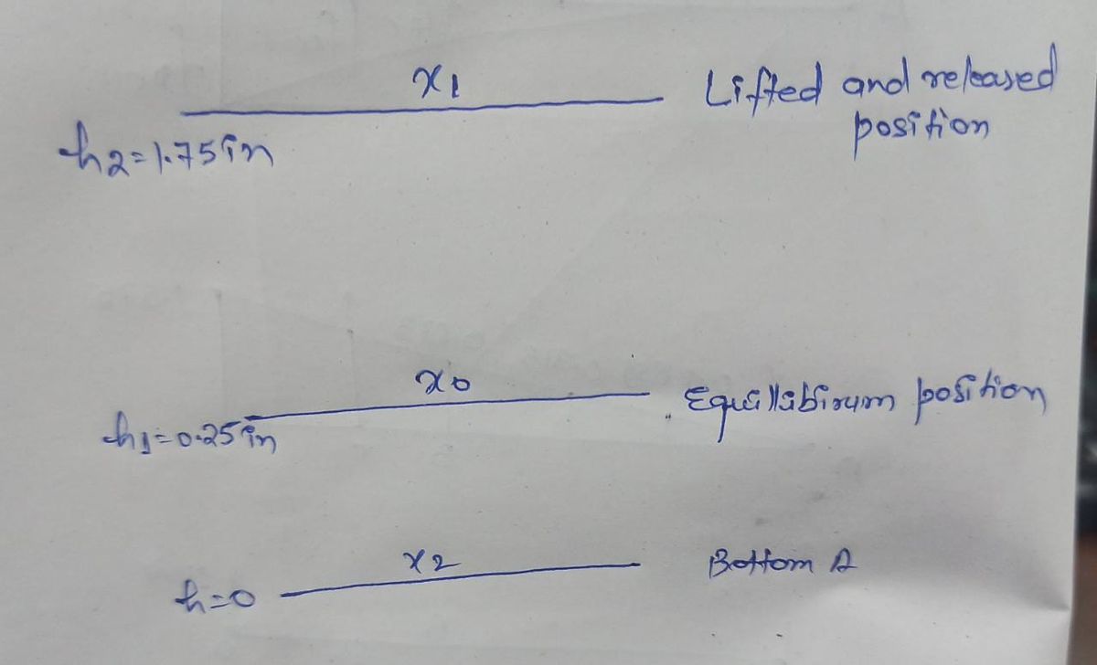
3. The bottom of a 5-lb vertical plunger is in the dashed position in resting
equilibrium against the spring with a stiffness k of 10 lb/in. The upper and
lower end of the spring is welded to the plunger and the base plate. (So, the
spring can carry compressive or tensile loads.) If the plunger is lifted 1.5
k = 10 lb/in.
inches above its equilibrium position and released from rest, what is its
velocity v as it strikes the button A. Neglect friction.
Expert Solution
arrow_forward
Step 1
The figure shows various position and compression of the plunger

The spring Stiffness k
In equilibrium position, the weight of the plunger is equal to restoring force in the spring
Trending nowThis is a popular solution!
Step by stepSolved in 2 steps with 1 images

Knowledge Booster
Learn more about
Need a deep-dive on the concept behind this application? Look no further. Learn more about this topic, civil-engineering and related others by exploring similar questions and additional content below.Similar questions
- water 3cm D=5 cm Mereury The tank in the has a 5 cm diameter plug at the bottom.on the rrght. All fluids are at zóc The Plag will pup out if the hydrestatic force is 30 for this condition what will be the readineg h ont Meicury mahometer on the left side2arrow_forwardIf the Spring DB has an unstretched length of 4.6 m and a stiffness of 201 N/m, determine the mass of the crate at A. Use: g = 9.81 m/s² Useful formula: F = kx 3m -3m- X - 4m wwwwwww. OBarrow_forwardIf the clamping force at G is 900 N, determine the horizontal force F that must be applied perpendicular to the handle of the lever at E. The mean diameter and lead of both single square-threaded screws at C and D are 25 mm and 5 mm, respectively. The coefficient of static friction is μ = 0.3. Answer: F = 66.7N 200 mm- -200 mm OA C 125 mmarrow_forward
- 4 - Two circular shafts are connected via a gear assembly as shown in the figure. Shaft 1 is fixed to a wall at point A. Torque T is applied to shaft 2 at point D. Shaft 1 is made of steel with a shear modulus of 85 GPa; shaft 2 is made of aluminum with a shear modulus of 28 GPa. The other relevant paramters are indicated alongside the figure. The shafts are restrained by bearings such that they do not undergo bending (i.e., it is a case of pure torsion). Determine the angular rotation at point D relative to that at point A. Shafts L₁=1.5m; L₂=1m r=50mm; ₂= 25 mm gear radii R₁-200mm; R₂=40mm Torque T=4KN-m Li C L2 * assume the gears to be rigid Tarrow_forwardRead the question carefully and give me right solution with clear calculationsarrow_forwardQ3: . A crank built up from cylindrical sections by welding required a loading of 250 lb to overcome the resistance when in the post- tion shown. (a) Compute the maximum normal and shear stresses induced in the section A-A. (b) Determine the maximum shear stresses induced in parts I, II, and III. Ans. (a) (max) = 29,000 psi, T(max) = 15,000 psi (b) 10,550 psi for part I, 6880 psi for II, 15,000 psi for III --A III II 1 Dia. Dia. Fig. 2-38 250 lb 150 "Dia.arrow_forward
- For the gear train shown, the diameters of the three solid shafts are: daB – 20 mm dcp – 25 mm der – 40 mm Knowing that for each shaft the allowable shearing stress is 60 MPa, determine the largest torque T that can be applied. 30 mm - 75 mm 30 mm 90 mmarrow_forwardThe following tubular A36 steel shaft has an inner diameter of 25mm and an outer diameter of 35mm under the following loading condition. Determine the angle of twist of the end V. Consider: GA-36 = 75 GPa 1) What would happen if a solid shaft was used? 2) As a designer, do you recommend a solid or tubular shaft for the loading above? Why?arrow_forward
arrow_back_ios
arrow_forward_ios
Recommended textbooks for you

 Structural Analysis (10th Edition)Civil EngineeringISBN:9780134610672Author:Russell C. HibbelerPublisher:PEARSON
 Principles of Foundation Engineering (MindTap Cou...Civil EngineeringISBN:9781337705028Author:Braja M. Das, Nagaratnam SivakuganPublisher:Cengage Learning
 Fundamentals of Structural AnalysisCivil EngineeringISBN:9780073398006Author:Kenneth M. Leet Emeritus, Chia-Ming Uang, Joel LanningPublisher:McGraw-Hill Education
 Traffic and Highway EngineeringCivil EngineeringISBN:9781305156241Author:Garber, Nicholas J.Publisher:Cengage Learning


Structural Analysis (10th Edition)
Civil Engineering
ISBN:9780134610672
Author:Russell C. Hibbeler
Publisher:PEARSON

Principles of Foundation Engineering (MindTap Cou...
Civil Engineering
ISBN:9781337705028
Author:Braja M. Das, Nagaratnam Sivakugan
Publisher:Cengage Learning

Fundamentals of Structural Analysis
Civil Engineering
ISBN:9780073398006
Author:Kenneth M. Leet Emeritus, Chia-Ming Uang, Joel Lanning
Publisher:McGraw-Hill Education


Traffic and Highway Engineering
Civil Engineering
ISBN:9781305156241
Author:Garber, Nicholas J.
Publisher:Cengage Learning