Introductory Circuit Analysis (13th Edition)
13th Edition
ISBN: 9780133923605
Author: Robert L. Boylestad
Publisher: PEARSON
expand_more
expand_more
format_list_bulleted
Question

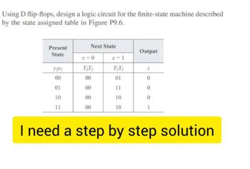
Transcribed Image Text:Using D flip-flops, design a logic circuit for the finite-state machine described
by the state assigned table in Figure P9.6.
Present
Next State
Output
State
x=0
x=1
Y2V1
Y2Y1
Y2Y1
Z
00
00
01
01
10
88
00
11
00
00
10
0
11
00
10
1
I need a step by step solution
Expert Solution
This question has been solved!
Explore an expertly crafted, step-by-step solution for a thorough understanding of key concepts.
Step by stepSolved in 3 steps with 4 images

Knowledge Booster
Learn more about
Need a deep-dive on the concept behind this application? Look no further. Learn more about this topic, electrical-engineering and related others by exploring similar questions and additional content below.Similar questions
- Q18 Find the expression for the output of the logic circuits shown in Figure below. A DAD C B Farrow_forward3.) The design size of the synchronous counter sequential (sequential) logic circuit. It will count from 0 to 9 and the son of your student number will not count decimals in two digits. A. List the process steps that you will apply in the design approach. Create the State Chart and State Chart. B. Design the sequential circuit using JK Flip-Flop. Explain each step. Show that it has performed the desired action. last digit student num: 0 4 " Not : I want the solution to contain tables and equations, and the electrical circuit resulting from tables and equations, as in the picture that I attached,And if possible, I want the solution on paper if possible.arrow_forwardplease help just answer as much as you can, no need to complete all. thank youarrow_forward
- Nodal analysis is based on KCL, which states that at any node, the sum of entering currents equals to the sum of leaving currents. Based on this idea, what are KCL equations for node 1 and node 2? 20 V/+ 59 www 12 O Node 1: 11+12-13 Node 2: 13+1s=14 O Node 1: 11-12+13 Node 2: 13+1s=14 O Node 1: 11+12-13 Node2: 13+14=1s O Node 1: 11+13=12 Node 2: 13-Is+14 V1 www 10 92 www 13 10 2 3 'Hi 14 V2 2022 Is 4 Aarrow_forward9.6 Using D flip-flops, design a logic circuit for the finite-state machine described by the state assigned table in Figure P9.6. Present Next State State Output x=0 x=1 Y2V1 Y₂Y Y2Y1 Z 00 00 01 0 01 00 11 0 10 00 10 0 11 00 10 1 Figure P9.6arrow_forward
arrow_back_ios
arrow_forward_ios
Recommended textbooks for you
 Introductory Circuit Analysis (13th Edition)Electrical EngineeringISBN:9780133923605Author:Robert L. BoylestadPublisher:PEARSON
 Delmar's Standard Textbook Of ElectricityElectrical EngineeringISBN:9781337900348Author:Stephen L. HermanPublisher:Cengage Learning
 Programmable Logic ControllersElectrical EngineeringISBN:9780073373843Author:Frank D. PetruzellaPublisher:McGraw-Hill Education
 Fundamentals of Electric CircuitsElectrical EngineeringISBN:9780078028229Author:Charles K Alexander, Matthew SadikuPublisher:McGraw-Hill Education
 Electric Circuits. (11th Edition)Electrical EngineeringISBN:9780134746968Author:James W. Nilsson, Susan RiedelPublisher:PEARSON
 Engineering ElectromagneticsElectrical EngineeringISBN:9780078028151Author:Hayt, William H. (william Hart), Jr, BUCK, John A.Publisher:Mcgraw-hill Education,

Introductory Circuit Analysis (13th Edition)
Electrical Engineering
ISBN:9780133923605
Author:Robert L. Boylestad
Publisher:PEARSON

Delmar's Standard Textbook Of Electricity
Electrical Engineering
ISBN:9781337900348
Author:Stephen L. Herman
Publisher:Cengage Learning

Programmable Logic Controllers
Electrical Engineering
ISBN:9780073373843
Author:Frank D. Petruzella
Publisher:McGraw-Hill Education

Fundamentals of Electric Circuits
Electrical Engineering
ISBN:9780078028229
Author:Charles K Alexander, Matthew Sadiku
Publisher:McGraw-Hill Education

Electric Circuits. (11th Edition)
Electrical Engineering
ISBN:9780134746968
Author:James W. Nilsson, Susan Riedel
Publisher:PEARSON

Engineering Electromagnetics
Electrical Engineering
ISBN:9780078028151
Author:Hayt, William H. (william Hart), Jr, BUCK, John A.
Publisher:Mcgraw-hill Education,