
Elements Of Electromagnetics
7th Edition
ISBN: 9780190698614
Author: Sadiku, Matthew N. O.
Publisher: Oxford University Press
expand_more
expand_more
format_list_bulleted
Related questions
Concept explainers
Question
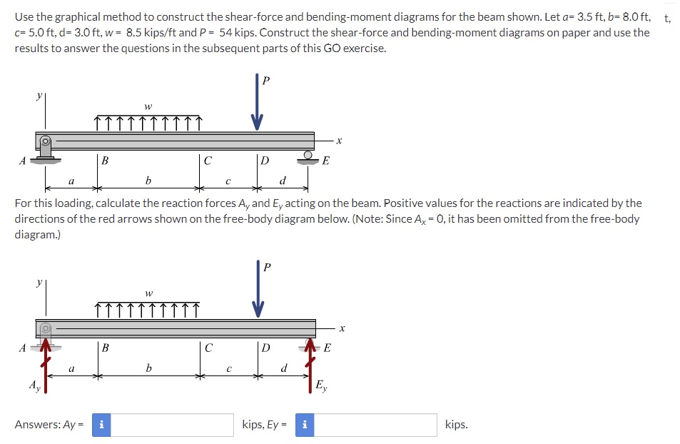

Transcribed Image Text:Use the graphical method to construct the shear-force and bending-moment diagrams for the beam shown. Let a= 3.5 ft, b= 8.0 ft, t,
c= 5.0 ft, d= 3.0 ft, w = 8.5 kips/ft and P = 54 kips. Construct the shear-force and bending-moment diagrams on paper and use the
results to answer the questions in the subsequent parts of this GO exercise.
P
В
D
E
b
d
For this loading, calculate the reaction forces A, and E, acting on the beam. Positive values for the reactions are indicated by the
directions of the red arrows shown on the free-body diagram below. (Note: Since A = 0, it has been omitted from the free-body
diagram.)
P
B
C
E
b
d
E,
Answers: Ay =
i
kips, Ey =
i
kips.
Expert Solution
This question has been solved!
Explore an expertly crafted, step-by-step solution for a thorough understanding of key concepts.

This is a popular solution

Trending nowThis is a popular solution!

Step by stepSolved in 4 steps with 4 images

Knowledge Booster


Learn more about
Need a deep-dive on the concept behind this application? Look no further. Learn more about this topic, mechanical-engineering and related others by exploring similar questions and additional content below.Similar questions
- Note: Include all necessary free-body diagrams. Q.1) (a) Find the support reactions of the beam shown below. (b) Find the shear-force and the bending-moment in the beam at point B. (c) Write the expressions for shear-force (V) and bending-moment (M) for the beam as a function of distant 'x' from the left-end support of the beam. A | 1 100 lb/ft 4 ft 4 ft B 300 lb C O 1 2 ft 2 ft Darrow_forwardConstruct the shear and moment diagrams for the loaded beam shown. After you have the diagrams, answer the questions. 1.2 kN/m W A Questions: Atx 1.1 m, V = W = w₁+kx² 1.9 kN/m 4.5 m x KN, M= i kN·m At x = 3.7 m, V = i KN, M= The absolute value of the maximum shear Vmax force is The absolute value of the maximum bending moment is Mmax i II kN·m KN x = r KN-m, x = rarrow_forwardPlease do not round off in all computations and box all final answers Conduct the following using either Double Integration Method, Moment Area Method, or Conjugate Beam Method Let El be constant. Given that from Point A, x = 8.12 m. What is the value of El(y)? Given that from Point A, x = 5.59 m. What is the value of El (y')? Given that from Point A, x = 4.92 m. What is the value of El(y)? Given that from Point A, x = 9.37 m. What is the value of El (y')? 61 KN 2.35 m 37 KN/m 30 KN/m 2.45 m A B 4.70 m 5.58 marrow_forward
- A force (FCD = 4.49 kN) is applied to a utility pole as shown.a) Write an algebraic expression with appropriate subscripts for the moment about the line passing through OF. What alternate moment arms could be used?b) Create a 3x3 determinant for the moment about line OF and solve. What does the sign of your answer indicate?c) Find the shortest distance between line OF and the line of action of the force.d) Find the 3D angle between OF and CD.arrow_forwardNeeds Complete typed solution with 100 % accuracy. Handwritten solution is completely prohibited.arrow_forwardsolve all parts. show all steps/solutions. show equations for shear and moment diagramsarrow_forward
- Draw complete shear force and bending moment diagrams for the beam. Label all graphs with the appropriate units. All work must be shown that led to the construction of your diagrams. 4) 6 kN 4 kN/m 20 kN-m 6 m 6 m 6 marrow_forwardBonus Question: worth up to 20% additional on this assignment: Solve for shear and bending moment distribution on the beam below. Just write the equations for shear and bending moment as a function of distance from the left hand side (wall side) of the beam. Note that the cosine function is automatically changing the direction of the load (downward vs. upward) along the length of the beam. 4 cosarrow_forwardPLEASE SHOW THE COMPLETE SOLUTION. CORRECT ANSWERS ARE SHOWN BELOW FOR YOUR REFERENCE. THANK YOU!arrow_forward
- Draw the shear and moment diagrams for the beam.arrow_forwardQuestion 13 Use the diagram shown above. Given • D₁ = 9 ft D₂=7 ft D₂ 3 D3-4 ft • W = 100 #/ft P = 800 # D. 1 D₂ X W P Solve for the internal moment at X. Note: Enter the numerical value only for your calculation results. You'll be asked to specify the unit for your calculation result in the following question. (This is due to Canvas' lack of ability to require units for calculation question.)arrow_forwardWhen a beam section is subjected to a shear load, a shear stress distribution is developed on the section. The distribution of the shear stress is not linear. Elasticity theory can be used to calculate the shear stress at any point. However, a simpler method can be used to calculate the average shear stress across the width of the section, a distance y above or below the neutral axis. The average VQ shear stress is given by T = Here V is the shear It force on the section, I is the moment of inertia of the entire section about the neutral axis, and t is the width of the section at the distance y where the shear stress is being calculated. Q is the product of the area of the section above (or below) y and the distance from the neutral axis to the centroid of that area (Figure 1). In short, Q is the moment of the area about the neutral axis. I Figure 1 of 1 An I-beam has a flange width b = 250 mm, height h = 250 mm, web thickness tw = 9 mm, and flange thickness tf = 14 mm. Use the…arrow_forward
arrow_back_ios
SEE MORE QUESTIONS
arrow_forward_ios
Recommended textbooks for you
- Elements Of ElectromagneticsMechanical EngineeringISBN:9780190698614Author:Sadiku, Matthew N. O.Publisher:Oxford University Press
 Mechanics of Materials (10th Edition)Mechanical EngineeringISBN:9780134319650Author:Russell C. HibbelerPublisher:PEARSON
 Thermodynamics: An Engineering ApproachMechanical EngineeringISBN:9781259822674Author:Yunus A. Cengel Dr., Michael A. BolesPublisher:McGraw-Hill Education
  Control Systems EngineeringMechanical EngineeringISBN:9781118170519Author:Norman S. NisePublisher:WILEY
 Mechanics of Materials (MindTap Course List)Mechanical EngineeringISBN:9781337093347Author:Barry J. Goodno, James M. GerePublisher:Cengage Learning
 Engineering Mechanics: StaticsMechanical EngineeringISBN:9781118807330Author:James L. Meriam, L. G. Kraige, J. N. BoltonPublisher:WILEY
Elements Of Electromagnetics
Mechanical Engineering
ISBN:9780190698614
Author:Sadiku, Matthew N. O.
Publisher:Oxford University Press
Mechanics of Materials (10th Edition)
Mechanical Engineering
ISBN:9780134319650
Author:Russell C. Hibbeler
Publisher:PEARSON
Thermodynamics: An Engineering Approach
Mechanical Engineering
ISBN:9781259822674
Author:Yunus A. Cengel Dr., Michael A. Boles
Publisher:McGraw-Hill Education
Control Systems Engineering
Mechanical Engineering
ISBN:9781118170519
Author:Norman S. Nise
Publisher:WILEY
Mechanics of Materials (MindTap Course List)
Mechanical Engineering
ISBN:9781337093347
Author:Barry J. Goodno, James M. Gere
Publisher:Cengage Learning
Engineering Mechanics: Statics
Mechanical Engineering
ISBN:9781118807330
Author:James L. Meriam, L. G. Kraige, J. N. Bolton
Publisher:WILEY