Elements Of Electromagnetics
7th Edition
ISBN: 9780190698614
Author: Sadiku, Matthew N. O.
Publisher: Oxford University Press
expand_more
expand_more
format_list_bulleted
Concept explainers
Question
In order to determine the magnitude of the internal forces, a FBD must be cut.
It is difficult to determine where a cut should be made in order to reveal the Maximum Internal Forces, thus we have put the distance to the cut in terms of 'x', and plot the equation.
In my lecture we took a generic portion of a Beam and applied equilibrium and saw that Loading, Shear and Moment are related to each through differential equations. Change in Shear is the Area under the Loading diagram. Change in Moment is the Area under the Shear Diagram.
Using Graphic Integration draw the shear and moment diagrams for the given beams and loading.

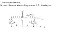
Transcribed Image Text:The Reactions are Given.
Draw the Shear and Moment Diagrams and deflection diagram
5K
W=1/PT.
7.8k
13.2k
b
Expert Solution
This question has been solved!
Explore an expertly crafted, step-by-step solution for a thorough understanding of key concepts.
Step by stepSolved in 3 steps with 3 images

Knowledge Booster
Learn more about
Need a deep-dive on the concept behind this application? Look no further. Learn more about this topic, mechanical-engineering and related others by exploring similar questions and additional content below.Similar questions
- For the loaded beam shown in Figure below : 2.1.Determine the reaction forces at the points of support of the beam in Figure Q2 above by applying the principle of equilibrium of moments and start your solution by drawing free body diagram of the beam. 2.2. Develop the equations for shear force and bending moment for the spans AB, BC and CD of the loaded beam shown above and for each equation developed, determine the values of shear forces and bending moment at the points A, B, C and D 2.3. Draw the shear force and bending moment diagrams for the loaded beam shown above.arrow_forwardPLEASE ?? ANSWER ?Part 1 For the simply supported beam subjected to the loading shown, derive equations for the shear force V and the bending moment M for any location in the beam. (Place the origin at point A) Let a= 3.00 m, b= S.00 m. PB= 35kN, and PC = 65kN. Construct the shear force and bending-moment diagrams on paper and use t he results to answer the quest ions in the subsequent parts of this GO exercise. Calculate the reaction forces Ay and Dy acting on the beam. Positive values for the reactions are indicated by the directions of the red arrows shown on the free-body diagram below. (Note: Since Ax = 0, it has been omitted from the free-body diagram.) Please Answer: Ay = kN Dy = kN ?Part 2 Determine the shear force acting at each of the following locations: (a)x = 2 m (b)x =4m (c). x = 8 m Note that x = 0 at support A When entering your answers. use the shear-force sign convention detailed in Section 7.2. Please Answer: (a) V= kN (b) V=…arrow_forwardPart (b)arrow_forward
- The textbook we use for this class is "Shigley's Mechanical Engineering Design", Richard G. Budynas, J. Keith Nisbett, Please help me solve this mechanical engineering problem. Thank you.arrow_forwardFor the cantilever beam shown in the figure below, invoke the equilibrium of cut free-body sections of the beam to (a) write equations for the shear force and bending moment distributions as functions of x. Include a free-body diagram of each cut section and force and moment balance calculations. Examine the shear force and bending moment formulas and deduce the sign of the deformation within each inter- val. Include a sketch of a deformed material element that illustrates the shear and bending deformation within the interval. (b) Find the shear force of the largest magnitude in the beam and state where it occurs within the beam. (c) Find the bending moment of the largest magnitude in the beam and state where it occurs within the beam. 200 N/m 0.6 m- X 600 N 0.2 m 0.2 marrow_forwardFind the shear force at point A, (VA) in kN. Find the bending moment at point A,(MA) and point B,(MB) in kNm. Find the shear force at point B,(VB) in kN.arrow_forward
arrow_back_ios
arrow_forward_ios
Recommended textbooks for you
 Elements Of ElectromagneticsMechanical EngineeringISBN:9780190698614Author:Sadiku, Matthew N. O.Publisher:Oxford University Press
 Mechanics of Materials (10th Edition)Mechanical EngineeringISBN:9780134319650Author:Russell C. HibbelerPublisher:PEARSON
 Thermodynamics: An Engineering ApproachMechanical EngineeringISBN:9781259822674Author:Yunus A. Cengel Dr., Michael A. BolesPublisher:McGraw-Hill Education
 Control Systems EngineeringMechanical EngineeringISBN:9781118170519Author:Norman S. NisePublisher:WILEY
 Mechanics of Materials (MindTap Course List)Mechanical EngineeringISBN:9781337093347Author:Barry J. Goodno, James M. GerePublisher:Cengage Learning
 Engineering Mechanics: StaticsMechanical EngineeringISBN:9781118807330Author:James L. Meriam, L. G. Kraige, J. N. BoltonPublisher:WILEY

Elements Of Electromagnetics
Mechanical Engineering
ISBN:9780190698614
Author:Sadiku, Matthew N. O.
Publisher:Oxford University Press

Mechanics of Materials (10th Edition)
Mechanical Engineering
ISBN:9780134319650
Author:Russell C. Hibbeler
Publisher:PEARSON

Thermodynamics: An Engineering Approach
Mechanical Engineering
ISBN:9781259822674
Author:Yunus A. Cengel Dr., Michael A. Boles
Publisher:McGraw-Hill Education

Control Systems Engineering
Mechanical Engineering
ISBN:9781118170519
Author:Norman S. Nise
Publisher:WILEY

Mechanics of Materials (MindTap Course List)
Mechanical Engineering
ISBN:9781337093347
Author:Barry J. Goodno, James M. Gere
Publisher:Cengage Learning

Engineering Mechanics: Statics
Mechanical Engineering
ISBN:9781118807330
Author:James L. Meriam, L. G. Kraige, J. N. Bolton
Publisher:WILEY