Introductory Circuit Analysis (13th Edition)
13th Edition
ISBN: 9780133923605
Author: Robert L. Boylestad
Publisher: PEARSON
expand_more
expand_more
format_list_bulleted
Question
SOLVE BY AND NOT USING CHAT GPT OTHERWISE DOWNVOTE

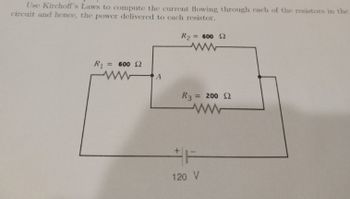
Transcribed Image Text:Use Kirchoff's Laws to compute the current flowing through each of the resistors in the
circuit and hence, the power delivered to each resistor.
R2
= 600 2
ww
R₁ = 600 2
www
A
R3 = 200 2
ww
F
120 V
Expert Solution
This question has been solved!
Explore an expertly crafted, step-by-step solution for a thorough understanding of key concepts.
Step by stepSolved in 2 steps with 3 images

Knowledge Booster
Similar questions
- Q4) Determine the current through each resistor in the circuit of Figure R₁ 680 www R₂ 330 w R₁ 22092 w 10 mAarrow_forwardResistors Circuits I Each of the circuits below consists of a battery and several resistors. Several of the voltages, currents, and resistances are indicated. Use both of Kirchoff's Laws and Ohm's Law to determine as many of the other voltages, currents, and resistances as possible.arrow_forwardPlease can you help me and solve questionsarrow_forward
- Confused on how to measure each resistors current using tinkercad...can someone help me with this?arrow_forwardDetermine the voltage V1 in Volts for the following circuit with component values ISRC = 1.5 mA, VSRC = 7 V, R1 = 2.2 kQ, R2 = 3.4 k2, and R3 = 1.0 kQ. 11 Vsrc Isrc + V1 + R1 m R2 R3 m 12 13arrow_forwardFInd VAarrow_forward
- Resistors Circuits I Each of the circuits below consists of a battery and several resistors. Several of the voltages, currents, and resistances are indicated. Use both of Kirchoff's Laws and Ohm's Law to determine as many of the other voltages, currents, and resistances as possible.arrow_forwardIn the following figure(Figure 1), R1 =6.00 , Ra = 6.00 , and R3 =6.00 2. The battery has negligible internal resistance. The current Ia through Rg is 5.00 A Part A What is the current I, through R1? Express your answer with the appropriate units. HA I = Value A Submit Request Answer Figure K 1 of 1 Part B What is the current Iz through R3? R1 Express your answer with the appropriate units. R2 HA ? I3 = Value A R3 Submit Request Answer 近arrow_forwardSolve it fast plzarrow_forward
- Please answer this with in 30 mins ! I will upvote !arrow_forwardDetermine the voltage V1 in Volts for the following circuit with component values ISRC = 1.6 mA, VSRC = 6 V, R1 = 2.3 k2, R2 = 3.5 kQ, and R3 = 1.3 kQ. Vsrc + R1 w R2 w Isrc V1 + R3 www 11 12 4 13arrow_forwardThe figure shows an electric circuit which contains a double switch labelled by S. When the switch is in the position 11' the ammeter reads I = 6 A, and when the switch is in position 22' the reading is I1 =3A. What is the reading on the ammeter when the switch is in position 33'? The electromotive forces E of the two batteries are equal, their internal resistances and the internal resistance of the ammeter are R, R, 03 E N R, 03' negligible. Earrow_forward
arrow_back_ios
SEE MORE QUESTIONS
arrow_forward_ios
Recommended textbooks for you
 Introductory Circuit Analysis (13th Edition)Electrical EngineeringISBN:9780133923605Author:Robert L. BoylestadPublisher:PEARSON
 Delmar's Standard Textbook Of ElectricityElectrical EngineeringISBN:9781337900348Author:Stephen L. HermanPublisher:Cengage Learning
 Programmable Logic ControllersElectrical EngineeringISBN:9780073373843Author:Frank D. PetruzellaPublisher:McGraw-Hill Education
 Fundamentals of Electric CircuitsElectrical EngineeringISBN:9780078028229Author:Charles K Alexander, Matthew SadikuPublisher:McGraw-Hill Education
 Electric Circuits. (11th Edition)Electrical EngineeringISBN:9780134746968Author:James W. Nilsson, Susan RiedelPublisher:PEARSON
 Engineering ElectromagneticsElectrical EngineeringISBN:9780078028151Author:Hayt, William H. (william Hart), Jr, BUCK, John A.Publisher:Mcgraw-hill Education,

Introductory Circuit Analysis (13th Edition)
Electrical Engineering
ISBN:9780133923605
Author:Robert L. Boylestad
Publisher:PEARSON

Delmar's Standard Textbook Of Electricity
Electrical Engineering
ISBN:9781337900348
Author:Stephen L. Herman
Publisher:Cengage Learning

Programmable Logic Controllers
Electrical Engineering
ISBN:9780073373843
Author:Frank D. Petruzella
Publisher:McGraw-Hill Education

Fundamentals of Electric Circuits
Electrical Engineering
ISBN:9780078028229
Author:Charles K Alexander, Matthew Sadiku
Publisher:McGraw-Hill Education

Electric Circuits. (11th Edition)
Electrical Engineering
ISBN:9780134746968
Author:James W. Nilsson, Susan Riedel
Publisher:PEARSON

Engineering Electromagnetics
Electrical Engineering
ISBN:9780078028151
Author:Hayt, William H. (william Hart), Jr, BUCK, John A.
Publisher:Mcgraw-hill Education,