
Introductory Circuit Analysis (13th Edition)
13th Edition
ISBN: 9780133923605
Author: Robert L. Boylestad
Publisher: PEARSON
expand_more
expand_more
format_list_bulleted
Related questions
Question
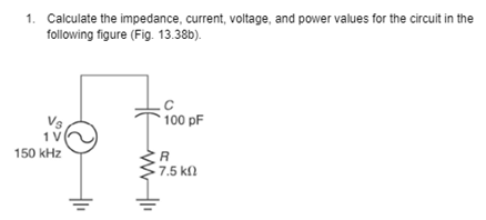

Transcribed Image Text:1. Calculate the impedance, current, voltage, and power values for the circuit in the
following figure (Fig. 13.38b).
150 kHz
100 pF
R
1 7.5 ΚΩ
Expert Solution
This question has been solved!
Explore an expertly crafted, step-by-step solution for a thorough understanding of key concepts.

Step by stepSolved in 2 steps

Knowledge Booster

Similar questions
- 13. A coil has a resistance of 6 ohms and an inductance of 0.02 H. When a non-inductive resistor is connected in series with the coil, the current drawn when connected to a 220 V DC source is equal to the current drawn by the coil alone across a 220 V, 60 Hz source. Determine the resistance of the non- inductive resistor. A) 3.63 0 B. 6.39 N C. 3.69 N D. 3.96 Narrow_forwardEX1) A boost converter has an input voltage of 5 V. The average output voltage is 15 V and the average load current is 0.5 A. If fs = 25kHz, L= 150 µH and C = 220 µF, determine (a)duty cycle (c) inductor peak current (d) output ripple voltage %3D (b) inductor ripple currentarrow_forwarda voltage waveform is shown below, where Vmax and Vmin are the maximum and minimum voltage values. Vmax = 8 V, and Vmin = -5; Calculate the amplitude of the voltage. enter your answer in V, and round it to two decimal places.arrow_forward
- Subject : Power electronics Please write handwritten Answerarrow_forwardFor the given circuit with a 12.81 Vpeak sinusoidal input, Vin, what is the value of Vout (in V) when input is a positive half cycle?Use practical model, Silicon diode. Vin Vout Round your answer to 2 decimal places. Rarrow_forwardQ1 Explain the following terms: (a) Sensor (1.5 marks) (b) Transducer (1.5 marks) (c) Instrument Q2 Q3 (2 marks) Based on Figure Q2, if the RTD sensor measurement is 57°C answer the following. (a) Calculate the output current from RTD sensor if the output range is 4 20mA. (2 marks) (b) Calculate the output voltage from the temperature controller if the output range is 0-10VDC. (2 marks) (c) Propose a type of sensor if the process temperature is increased to 1000°C. (1 marks) A capacitive displacement transducer is designed to determine the rotary position. from 0° 180° as shown in Figure Q3. The moving plate whose radius is 40mm is sandwiched between two fixed plates, spacing at Imm. The dielectric constant of air is k 1.The capacitive transducer is formulated as: where; (a) kA€。 farads k = dielectric constant A the area of the plate, in square meters €₁ = 8.854 × 10⁻¹² in farads per meter d = the plate spacing in meters Construct an equation of the change of the capacitance (F) when…arrow_forward
- 120 VRMS 1 Select one: OA. 360 VRMS OB. 40 VRMS OC. 80 VRMS OD. 240 VRMS لشما What is the secondary voltage if the turns ratio is 1:3?arrow_forwardA 43mH coil in series with a 1200 ohm resistor across a sine wave ac voltage source with a frequency of 6 kHz. The total impedance for the circuit is O 1620 46.5° ohm esc 2017 53.5° ohm 1200 53.5° ohm 2820 46.5° ohm ! 1 Q ← 2 W #3 C E $ 54 R G Search or type URL % 5 MacBook Pro T A 6 Y & 7 ☆ U * 8 + 1 ( 9 ( 0 ) 0 4) P + O = [ deletearrow_forwardAC xuf lac V ac 21. The simple AC powered circuit above is being measured for AC current and voltage across a 1uF capacitor. The measured current is 200mA and the measured voltage is 40V. (note: 2 separate questions follow) a. Calculate the capacitive reactance, Xc. b. Calculate the voltage frequency.arrow_forward
arrow_back_ios
SEE MORE QUESTIONS
arrow_forward_ios
Recommended textbooks for you
- Introductory Circuit Analysis (13th Edition)Electrical EngineeringISBN:9780133923605Author:Robert L. BoylestadPublisher:PEARSON
 Delmar's Standard Textbook Of ElectricityElectrical EngineeringISBN:9781337900348Author:Stephen L. HermanPublisher:Cengage Learning
 Programmable Logic ControllersElectrical EngineeringISBN:9780073373843Author:Frank D. PetruzellaPublisher:McGraw-Hill Education
  Fundamentals of Electric CircuitsElectrical EngineeringISBN:9780078028229Author:Charles K Alexander, Matthew SadikuPublisher:McGraw-Hill Education
 Electric Circuits. (11th Edition)Electrical EngineeringISBN:9780134746968Author:James W. Nilsson, Susan RiedelPublisher:PEARSON
 Engineering ElectromagneticsElectrical EngineeringISBN:9780078028151Author:Hayt, William H. (william Hart), Jr, BUCK, John A.Publisher:Mcgraw-hill Education,
Introductory Circuit Analysis (13th Edition)
Electrical Engineering
ISBN:9780133923605
Author:Robert L. Boylestad
Publisher:PEARSON
Delmar's Standard Textbook Of Electricity
Electrical Engineering
ISBN:9781337900348
Author:Stephen L. Herman
Publisher:Cengage Learning
Programmable Logic Controllers
Electrical Engineering
ISBN:9780073373843
Author:Frank D. Petruzella
Publisher:McGraw-Hill Education
Fundamentals of Electric Circuits
Electrical Engineering
ISBN:9780078028229
Author:Charles K Alexander, Matthew Sadiku
Publisher:McGraw-Hill Education
Electric Circuits. (11th Edition)
Electrical Engineering
ISBN:9780134746968
Author:James W. Nilsson, Susan Riedel
Publisher:PEARSON
Engineering Electromagnetics
Electrical Engineering
ISBN:9780078028151
Author:Hayt, William H. (william Hart), Jr, BUCK, John A.
Publisher:Mcgraw-hill Education,