Introductory Circuit Analysis (13th Edition)
13th Edition
ISBN: 9780133923605
Author: Robert L. Boylestad
Publisher: PEARSON
expand_more
expand_more
format_list_bulleted
Concept explainers
Question

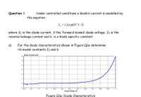
Transcribed Image Text:Under controlled conditions a diode's current is modelled by
the equation :
Question 1
I, = 1,(exp(kV)-1)
where Io is the diode current, V the 'forward biaseď diode voltage, Is is the
reverse leakage current and k is a diode specific constant.
a)
For the diode characteristics shown in Figure Qla determine
its model constants Is and k.
Diode Current (mA)
3
1
2uA
-1
-0.2
-0.1
0.1
0.2
D.3
0.4
D.5
0.6
0.7
0.8
0.9
1
Diode Voltaae M
Figure Qla: Diode Characteristics
Expert Solution
This question has been solved!
Explore an expertly crafted, step-by-step solution for a thorough understanding of key concepts.
Step by stepSolved in 2 steps with 1 images

Knowledge Booster
Learn more about
Need a deep-dive on the concept behind this application? Look no further. Learn more about this topic, electrical-engineering and related others by exploring similar questions and additional content below.Similar questions
- Draw and identify all the types of diode clippers (series and parallel) and clampers. Provide one solved problem each and the reference for each clipper/clamper circuit example.arrow_forwardA single phase – half wave controlled rectifier with freewheeling diode is supplying a load consisting series connected a resistor and an inductance from a 70.7V (RMS), 50HZ sinusoidal AC source. The firing delay of the thyristor is 90° and the load values are R=102, L=0.1 H. Define the load current expression and draw the load current by calculating for first two periods. And calculate the average values of the load voltage and current.arrow_forwardWrite the following for a Semiconverter rectifier with RL load: a) Draw the circuit diagram, supply voltage and the output voltage waveform. b) Explain why there is no negative output voltage even without freewheeling diode. c) Derive the expression for average output voltage.arrow_forward
- How tunneling takes place in Tunnel diode. Show and explain the V-I Characteristics of Tunnel diode with necessary diagrams.arrow_forwarddiode? Under what circumstances does the output voltage remain constant in a limiter circuit with Zener When does the Z-current Iz begin to flow? Under what circumstances is the limiting effect maintained even under load?arrow_forwardPlease show all workarrow_forward
- Q1 Figure Q1(a) is a full wave bridge circuit with a capacitor filter and the output waveform produced by the circuit is shown in Figure Q1(b). Assume all the diodes in the circuit have a forward voltage of 0.7 V. (a) Sketch the waveform in A, B, C and D as shown in Figure Q1(a).arrow_forward0:- Consider the circuit in Figure a) What type of circuit is this? b) Find and Sketch the voltage waveform across RL, assume the diodes are practical. c) If 100uf capacitor parallel with the resistor, calculate the ripple is connected factor I O o Darrow_forwardAnswer all the questions one by one and solve all the unknown values with correct detailsarrow_forward
- A p-type semiconductor joined to an n-type semiconductor ... Pick those that apply. Will not allow current to flow in either direction. Has electron current flowing from the n-type to the p-type material Makes a diode Allows positive current flow from the p-type to the n-type materialarrow_forwardDraw the input waveform and output waveform for the circuit given below with proper values marked in the figure. Assume D1 as germanium and D2 as silicon diodes. Input Vpp%3D20V, V1=3 V and V2=10 V. R D2 D1 Vin Vout V1 V2 Maximum voltage of output waveform Minimum voltage of output waveform Psarrow_forwardBase from the values given. Fill in the questions.arrow_forward
arrow_back_ios
SEE MORE QUESTIONS
arrow_forward_ios
Recommended textbooks for you
 Introductory Circuit Analysis (13th Edition)Electrical EngineeringISBN:9780133923605Author:Robert L. BoylestadPublisher:PEARSON
 Delmar's Standard Textbook Of ElectricityElectrical EngineeringISBN:9781337900348Author:Stephen L. HermanPublisher:Cengage Learning
 Programmable Logic ControllersElectrical EngineeringISBN:9780073373843Author:Frank D. PetruzellaPublisher:McGraw-Hill Education
 Fundamentals of Electric CircuitsElectrical EngineeringISBN:9780078028229Author:Charles K Alexander, Matthew SadikuPublisher:McGraw-Hill Education
 Electric Circuits. (11th Edition)Electrical EngineeringISBN:9780134746968Author:James W. Nilsson, Susan RiedelPublisher:PEARSON
 Engineering ElectromagneticsElectrical EngineeringISBN:9780078028151Author:Hayt, William H. (william Hart), Jr, BUCK, John A.Publisher:Mcgraw-hill Education,

Introductory Circuit Analysis (13th Edition)
Electrical Engineering
ISBN:9780133923605
Author:Robert L. Boylestad
Publisher:PEARSON

Delmar's Standard Textbook Of Electricity
Electrical Engineering
ISBN:9781337900348
Author:Stephen L. Herman
Publisher:Cengage Learning

Programmable Logic Controllers
Electrical Engineering
ISBN:9780073373843
Author:Frank D. Petruzella
Publisher:McGraw-Hill Education

Fundamentals of Electric Circuits
Electrical Engineering
ISBN:9780078028229
Author:Charles K Alexander, Matthew Sadiku
Publisher:McGraw-Hill Education

Electric Circuits. (11th Edition)
Electrical Engineering
ISBN:9780134746968
Author:James W. Nilsson, Susan Riedel
Publisher:PEARSON

Engineering Electromagnetics
Electrical Engineering
ISBN:9780078028151
Author:Hayt, William H. (william Hart), Jr, BUCK, John A.
Publisher:Mcgraw-hill Education,