
Structural Analysis
6th Edition
ISBN: 9781337630931
Author: KASSIMALI, Aslam.
Publisher: Cengage,
expand_more
expand_more
format_list_bulleted
Related questions
Question
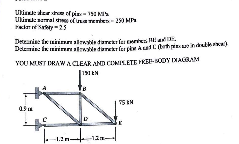

Transcribed Image Text:Ultimate shear stress of pins = 750 MPa
Ultimate normal stress of truss members = 250 MPa
Factor of Safety = 2.5
Determine the minimum allowable diameter for members BE and DE.
Determine the minimum allowable diameter for pins A and C (both pins are in double shear).
YOU MUST DRAW A CLEAR AND COMPLETE FREE-BODY DIAGRAM
150 kN
0.9 m
A
B
75 kN
C
m +
-1.2 m-
D
-1.2 m-
m→
E
SAVE
AI-Generated Solution
info
AI-generated content may present inaccurate or offensive content that does not represent bartleby’s views.
Unlock instant AI solutions
Tap the button
to generate a solution
to generate a solution
Click the button to generate
a solution
a solution
Knowledge Booster

Similar questions
- 5)Determine the forces in all members of the truss. There is a pin at A and a roller at D. In answers for truss forces remember you must always indicate if a member is in tension (T) or compression (C); for example, if there was a member JK carrying a 2 kip compressive load the answer would be FJ = 10 K (C) 3 m G 10 kN 6kN E -2.5 m- -1.5 m-1.5 m- -2.5 marrow_forwardStatics - Zero Force Members1. Identify the zero-force members in the truss shown. 2. Redraw the truss without the zero-force members included.arrow_forward*For the Howe bridge truss shown, d=11 ft,F1=3150 lb, F2=2150 lb, F3=2550 lb, and F4=4150 lb.* Pt A. Determine the forces in members CD, DH, and GH. Pt B. Determine the forces in members HI, BH, and BC.arrow_forward
- The two vertical steel [E = 200 GPa] rods that support rigid bar ABCD are initially free of stress. Rod (1) has an area of A1 = 410 mm2 and a length of L1 = 3.2 m. Rod (2) has an area of A2 = 355 mm2 and a length of L2 = 1.3 m. Assume dimensions of a = 3.4 m, b = 1.2 m, and c = 1.5 m. After a load of P = 50 kN is applied to the rigid bar at D, determine: (a) the normal stresses in rods (1) and (2) (b) the magnitude of the downward deflection of the rigid bar at D. y,v (2) L2 a B C D x,u Rigid bar |(1) Answer: (a) o1 = i MPa 02 = i MPa (b) VD = i mmarrow_forwardPlease help on the 3 questions in the photoarrow_forward
arrow_back_ios
arrow_forward_ios
Recommended textbooks for you
 Structural Analysis (10th Edition)Civil EngineeringISBN:9780134610672Author:Russell C. HibbelerPublisher:PEARSON
 Principles of Foundation Engineering (MindTap Cou...Civil EngineeringISBN:9781337705028Author:Braja M. Das, Nagaratnam SivakuganPublisher:Cengage Learning
 Fundamentals of Structural AnalysisCivil EngineeringISBN:9780073398006Author:Kenneth M. Leet Emeritus, Chia-Ming Uang, Joel LanningPublisher:McGraw-Hill Education
 Traffic and Highway EngineeringCivil EngineeringISBN:9781305156241Author:Garber, Nicholas J.Publisher:Cengage Learning
Structural Analysis (10th Edition)
Civil Engineering
ISBN:9780134610672
Author:Russell C. Hibbeler
Publisher:PEARSON
Principles of Foundation Engineering (MindTap Cou...
Civil Engineering
ISBN:9781337705028
Author:Braja M. Das, Nagaratnam Sivakugan
Publisher:Cengage Learning
Fundamentals of Structural Analysis
Civil Engineering
ISBN:9780073398006
Author:Kenneth M. Leet Emeritus, Chia-Ming Uang, Joel Lanning
Publisher:McGraw-Hill Education
Traffic and Highway Engineering
Civil Engineering
ISBN:9781305156241
Author:Garber, Nicholas J.
Publisher:Cengage Learning