Elements Of Electromagnetics
7th Edition
ISBN: 9780190698614
Author: Sadiku, Matthew N. O.
Publisher: Oxford University Press
expand_more
expand_more
format_list_bulleted
Question

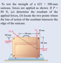
Transcribed Image Text:To test the strength of a 625 × 500-mm suitcase, forces are applied as shown. If \( P = 88 \, \text{N} \), (a) determine the resultant of the applied forces, (b) locate the two points where the line of action of the resultant intersects the edge of the suitcase.
### Diagram Explanation:
The image shows a suitcase with dimensions of 625 mm in width and 500 mm in height. Four forces are applied at specific points on the suitcase:
1. **212 N Force:** Applied at point A (top-left edge) at a 45-degree angle upward.
2. **100 N Force:** Applied horizontally towards the right at point A (top-left edge).
3. **88 N Force (represented as P):** Applied vertically downward at point B, which is located 450 mm to the right of point A.
4. **180 N Force:** Applied vertically upward from point D, which is located 500 mm directly below point B (bottom-right edge).
### Dimensions Marked:
1. The point B is 450 mm horizontally to the right of point A.
2. The point D is 500 mm vertically below point B.
### Task:
1. **Determine the Resultant of the Applied Forces:**
- Calculate the vector sum of the forces considering both magnitude and direction.
2. **Locate the Points where the Line of Action of the Resultant Intersects the Edge of the Suitcase:**
- Identify the locations on the edge of the suitcase where the line of action of the resultant intersects.
### Points:
- Point A: Top-left corner
- Point B: 450 mm right from Point A
- Point D: Bottom edge directly below Point B
This explanation covers the necessary points, forces, and measurements involved in the problem as per the provided diagram.

Transcribed Image Text:**Analyzing Wind Loading on a Building Frame**
**Problem Statement:**
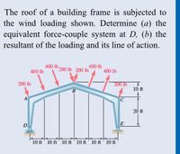
The roof of a building frame is subjected to the wind loading as depicted in the figure. The objectives are to determine:
(a) The equivalent force-couple system at point D.
(b) The resultant of the loading and its line of action.
**Diagram Explanation:**
The image shows a diagram of a building frame with specific wind load forces indicated. The structure appears to be symmetrical with a triangular roof peaked at point B. The forces applied are as follows:
1. At the left edge (beside point A): A downward force of 200 lbs.
2. Moving from left to right at equal distances of 10 ft:
- First segment (left of peak): Downward forces of 400 lbs, 200 lbs, and upward force of 200 lbs.
- Second segment (right of peak): Downward forces of 400 lbs, 200 lbs, and upward force of 200 lbs.
3. At the right edge (beside point E): A downward force of 200 lbs.
The height measurements from the top of the frame to the bottom are also given - 20 ft total height and alternating 10 ft heights across different segments.
By analyzing the applied forces symmetrically around the peak and knowing the dimensional properties, students can solve for the equivalent force-couple system at point D, as well as determine the overall resultant force and its line of action for a comprehensive understanding of the wind loading effects on the building frame.
Expert Solution
This question has been solved!
Explore an expertly crafted, step-by-step solution for a thorough understanding of key concepts.
This is a popular solution
Trending nowThis is a popular solution!
Step by stepSolved in 4 steps with 4 images

Knowledge Booster
Learn more about
Need a deep-dive on the concept behind this application? Look no further. Learn more about this topic, mechanical-engineering and related others by exploring similar questions and additional content below.Similar questions
- A cable is connected to an L shaped arm OAB as shown. The magnitude off the tensile force on the cable is given as T = 2500 and angle between the segment AB of the L- shaped arm and cable = 91.229 degrees. ( use the vector approach ) A) determine the components of the tensile force on the cable which are parallel and perpendicular to segment AB of the L-shaped armarrow_forwardIf the resultant of the forces shown passes through point A, determine the magnitude of the unknown pulley tension T2. The pulley is welded to the frame and is therefore not free to rotate. 1.3 m 260 N Answer: T₂ = i 0.4 m A T₂ 827.32 1.7 m 59° 1440 N B 0.70 m 1.40 m 660 N 240 N Narrow_forwardDetermine the magnitude of the force exerted by the cable at B of the bar shown in Figure. 260 3.5 m 2300 N 2.8 m 3.3 marrow_forward
arrow_back_ios
arrow_forward_ios
Recommended textbooks for you
 Elements Of ElectromagneticsMechanical EngineeringISBN:9780190698614Author:Sadiku, Matthew N. O.Publisher:Oxford University Press
 Mechanics of Materials (10th Edition)Mechanical EngineeringISBN:9780134319650Author:Russell C. HibbelerPublisher:PEARSON
 Thermodynamics: An Engineering ApproachMechanical EngineeringISBN:9781259822674Author:Yunus A. Cengel Dr., Michael A. BolesPublisher:McGraw-Hill Education
 Control Systems EngineeringMechanical EngineeringISBN:9781118170519Author:Norman S. NisePublisher:WILEY
 Mechanics of Materials (MindTap Course List)Mechanical EngineeringISBN:9781337093347Author:Barry J. Goodno, James M. GerePublisher:Cengage Learning
 Engineering Mechanics: StaticsMechanical EngineeringISBN:9781118807330Author:James L. Meriam, L. G. Kraige, J. N. BoltonPublisher:WILEY

Elements Of Electromagnetics
Mechanical Engineering
ISBN:9780190698614
Author:Sadiku, Matthew N. O.
Publisher:Oxford University Press

Mechanics of Materials (10th Edition)
Mechanical Engineering
ISBN:9780134319650
Author:Russell C. Hibbeler
Publisher:PEARSON

Thermodynamics: An Engineering Approach
Mechanical Engineering
ISBN:9781259822674
Author:Yunus A. Cengel Dr., Michael A. Boles
Publisher:McGraw-Hill Education

Control Systems Engineering
Mechanical Engineering
ISBN:9781118170519
Author:Norman S. Nise
Publisher:WILEY

Mechanics of Materials (MindTap Course List)
Mechanical Engineering
ISBN:9781337093347
Author:Barry J. Goodno, James M. Gere
Publisher:Cengage Learning

Engineering Mechanics: Statics
Mechanical Engineering
ISBN:9781118807330
Author:James L. Meriam, L. G. Kraige, J. N. Bolton
Publisher:WILEY