Elements Of Electromagnetics
7th Edition
ISBN: 9780190698614
Author: Sadiku, Matthew N. O.
Publisher: Oxford University Press
expand_more
expand_more
format_list_bulleted
Question

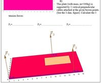
Transcribed Image Text:B)
This plate (with mass, m=500kg) is
supported by 3 vertical perpendicular
cables attached at the given brown points.
(See the 3-dim. figure). Calculate the 3
10
tension forces:
F1=.
F2=.
F;=
to 9)
15
16
12 13 14
6 7 8 9 10 11
1 2 3 4 5
2.
1
Expert Solution
This question has been solved!
Explore an expertly crafted, step-by-step solution for a thorough understanding of key concepts.
This is a popular solution
Trending nowThis is a popular solution!
Step by stepSolved in 4 steps with 3 images

Knowledge Booster
Similar questions
- B As indicated in the diagram above, a sign weighing 2210 N is suspended from a wall with a cable that is attached to the wall at a point 3.96 m (side A) above a horizontal beam that causes the sign to be a distance of 4.3 m from the wall (side B). What is the tension in the cable?arrow_forwardTwo weights, A and C, are fixed to a bar, B. Their masses are: A = 60 kg, B = 230 kg,C = 45 kg. B is, in turn, connected to a fixed vertical post by a hinge and a support cableD. The geometry of the system is shown at right. Treat weights A and C as point masses a)What is the tension in support cable D? Be sure to include a detailed freebody diagram to accompany your analysis.b) What is the magnitude of the force provided by the hinge?c) What is the moment of inertia of the A + B + C as a rigid system, for rotationabout the hinge? For analysis, break the beam into a short piece to the left of thehinge, and a separate longer piece to the right of the hinge. If the support cable D on should break,d) what is the angular acceleration of the beam and weights at the moment the cable breaks?e) what is the magnitude of the linear acceleration experienced by each of the weights, A and C, at moment the cable breaks?arrow_forwardProblem # 1 A 1ok For the pinned frame in the figure, calculate the pin forces acting at point B, on member BD (magnitude and direction). B dol 4'arrow_forward
- Q/1: A 10 m long vertical mast has a ball-and socket joint at A, and it is supported by two (2) cables, BD and BC as shown in Figure 1. A force 4 kN is applied at G. Draw the free body diagram (FBD) for the rigid body and determine: (a) The tensions in cables BD and BC (b) The reactions at the ball-and-socket joint at A (c) The projection of T, along the line BE (d) The angle between cable BD and line BE (e) The moment of T, along line CF T2 4 kN 5 m B 5 m T₁ 4m-F 74 m 12m xarrow_forwardNeed help please Include all units and stepsarrow_forwardProblem 4b: If the plate below weighs 500 N, find the tensions in the three cables. 1.5 m 1.6 m 2.5 m k.75 m*-1m- Xarrow_forward
arrow_back_ios
arrow_forward_ios
Recommended textbooks for you
 Elements Of ElectromagneticsMechanical EngineeringISBN:9780190698614Author:Sadiku, Matthew N. O.Publisher:Oxford University Press
 Mechanics of Materials (10th Edition)Mechanical EngineeringISBN:9780134319650Author:Russell C. HibbelerPublisher:PEARSON
 Thermodynamics: An Engineering ApproachMechanical EngineeringISBN:9781259822674Author:Yunus A. Cengel Dr., Michael A. BolesPublisher:McGraw-Hill Education
 Control Systems EngineeringMechanical EngineeringISBN:9781118170519Author:Norman S. NisePublisher:WILEY
 Mechanics of Materials (MindTap Course List)Mechanical EngineeringISBN:9781337093347Author:Barry J. Goodno, James M. GerePublisher:Cengage Learning
 Engineering Mechanics: StaticsMechanical EngineeringISBN:9781118807330Author:James L. Meriam, L. G. Kraige, J. N. BoltonPublisher:WILEY

Elements Of Electromagnetics
Mechanical Engineering
ISBN:9780190698614
Author:Sadiku, Matthew N. O.
Publisher:Oxford University Press

Mechanics of Materials (10th Edition)
Mechanical Engineering
ISBN:9780134319650
Author:Russell C. Hibbeler
Publisher:PEARSON

Thermodynamics: An Engineering Approach
Mechanical Engineering
ISBN:9781259822674
Author:Yunus A. Cengel Dr., Michael A. Boles
Publisher:McGraw-Hill Education

Control Systems Engineering
Mechanical Engineering
ISBN:9781118170519
Author:Norman S. Nise
Publisher:WILEY

Mechanics of Materials (MindTap Course List)
Mechanical Engineering
ISBN:9781337093347
Author:Barry J. Goodno, James M. Gere
Publisher:Cengage Learning

Engineering Mechanics: Statics
Mechanical Engineering
ISBN:9781118807330
Author:James L. Meriam, L. G. Kraige, J. N. Bolton
Publisher:WILEY