
Introductory Circuit Analysis (13th Edition)
13th Edition
ISBN: 9780133923605
Author: Robert L. Boylestad
Publisher: PEARSON
expand_more
expand_more
format_list_bulleted
Related questions
Question
thumb_up100%
only 1-3, will give like
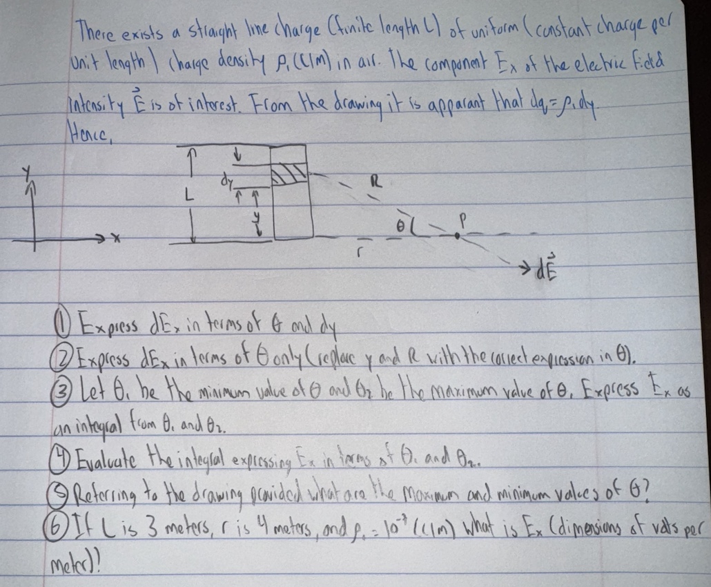

Transcribed Image Text:There exists a straight line charge (finite length L) of uniform (constant charge per
Unit length charge density P. (CIM) in air. The component Ex of the electric ficd
intensity E is of interest. From the drawing it is apparant that d₁ = p.dy-
Hence,
1
L
है
r
شاه
→ de
Express dEx in terms of & and dy
Express dEx in terms of Gonly (replace y and R with the correct expression in 6).
Let 6. be the minimum value of 0 and Or be the maximum value of e, Express Ex as
Lan integral from B. and 02.
①Evaluate the integral expressing Ex in terms of O. and On..
© Referring to the drawing provided what are the maximum and minimum values of G?
If Lis 3 meters, is 4 maters, and p₁ = 10% (CIM) what is Ex (dimensions of vals per
meter)!
Expert Solution
This question has been solved!
Explore an expertly crafted, step-by-step solution for a thorough understanding of key concepts.

Step by stepSolved in 2 steps with 1 images

Knowledge Booster

Similar questions
- The work done by the force F- da. - 3a, + 2a. Nin giving a InC charge a displacement of 10a, + 24 - 7a, m is ? (note: be aware of the sign for the given direction) (a) 103al (b) 60 nl (e) 64 n (d) 20 narrow_forwardFor the circuit shown in Figure:a. Determine the reluctance values and show themagnetic circuit, assuming that μ = 3,000μ0.b. Determine the inductance of the device.c. The inductance of the device can be modified bycutting an air gap in the magnetic structure. If a gapof 0.1 mm is cut in the arm of length l3, what is thenew value of inductance?d. As the gap is increased in size (length), what is thelimiting value of inductance? Neglect leakage fluxand fringing effects.arrow_forwardQ.3 (a) A capacitor's structure is made up of two conductors that are separated by a dielectric material. Describe the phenomenon that allow the flow of current through the dielectric material. Include in the description relevant mathematical derivation of the abovementioned phenomenon. (b) A capacitor such as illustrated in Figure Q.3 is constructed using copper as plate A and plate B plus a dielectric material with ɛ, 3.8 and o = 4 S/m between the plates. Potential difference plates A across is VAB (t) = Vo cos(2n x 10°t) V. Assume that Plate A and plate B carry charges +Q(t) and and -Q(t) respectively as well as fringing field at the edge of the plates can be ignored, determine: (i) Q(t) if the capacitance is 2.135 x 10⁻¹¹ F (ii) M(t) if electric field within the capacitor, E(t) = M(t) fV/m Based on Q.3(b)(ii), examine: (iii) Conduction current density and conduction current. UNIVE (iv) Displacement current density and displacement current. arch ASUS VivoBookarrow_forward
- Don't use ai to answer I will report you answerarrow_forward6- Why an insulator is represented as a capacitor C? What are the assumption modes?arrow_forward1. There is another method to find the time constant RC. For a discharging capacitor its voltage can RC be expressed as V(t) = V₂e . When time t = RC, V = Voe¹ = V.(0.368). If we have a discharging curve, we follow the curve to the point where the voltage is equal to 0.368V. The time corresponding to 0.386V, is the time constant, t = RC. V V₂ 0.368 V T Use your voltage data for R₁ = 10 k2 and determine the time constant. Show your work.arrow_forward
- 1. A thin rod of length W has uniform charge per length A. Find the electric potential (voltage) at the position P as shown. Assume V = 0 at r = o for problems on this worksheet. Use the integration variable u as defined in the diagram to write the voltage at point P. Include the limits of integration but you do not need to evaluate the integral. P Hint: break up the rod into small pieces of length du and use the point charge formula for the voltage due to the small piece dV = Kdq/r with dą and r written in terms of the givens à, L, z and integration variable u and du. W 3 du 0.arrow_forwardSolve both question.... It's objective type questions so as per bartlybe's guidelines you need solve both question.arrow_forwardThere is a nonuniform electric field given as: E = 15 - ɑ.V /m Determine the numerical value of the potential (voltage) at (5, 20, 9) with respect to (20, 4, 18). Draw a labeled sketch of the electric field orientation and the integration path a. b. c. Justify the sign of your potential using the sketch.arrow_forward
- 5. The parallel-plate capacitor in the figure below has square plates. The area of the pates is 4 m?. A current of 2.0 A charges the capacitor, producing a uniform electric field E between the plates, with E perpendicular to the plates. L Edge view Top view (a) What is the displacement-current, ia through the region between the plates? (b) What is dE/dt in this region? (c) What is the displacement current encircled by the square dashed path of edge length d= 1.25 m? (d) What is the value of $ B ds around this square dashed path?arrow_forwardI. SOLVE THE FOLLONING PROBLENS : A COPPER WIRE OF 0,3 Mm RAAUS HAS A LEN ETH OF 1. JOM- IF THE RESISTIVITY of cOpPER IS 1-7 x0 WHAT WOULD BE THE RESISTANOE OF THE WIRE? OF A 100m WIRE IS 1035 mm AND 3.7 OHMS. WHAT 2. THE DIAMETER THE REISTANCE IS IS THE CONDUCTIVITY 3. WHAT WILL BE THE VALUE OF A CAPACITOR WHEN IT HAS A CAPACITIVE REACTANCE OF 300R ANP to A 6o HZ. SUPPLY? IN FARADS IS CONNECTED 4. WHAT Is THE VALUE OF THE RESISTOR WITH THE FOLLOWING COLORS ? A. BROWN, BLACK, GOLD, REP B. BLUE YELON BROWN, SILVER PED, SILVER, BROWN, VIOET C. 5. AND t WHEN V 220V AND R= 50n WHEN I = 45 A WHEN V = 120V FIND V ANO R 80n AND AND E= 11A-arrow_forwardGiven that the electric field E has a triangular profile as shown in the figure below, and that the built-in potential, Vo, is given by the total area under the triangle, find an expression for the maximum electric field magnitude, Emax, in terms of the dopant concentrations and fundamental constants. E Emax ^ Xn -Xparrow_forward
arrow_back_ios
arrow_forward_ios
Recommended textbooks for you
- Introductory Circuit Analysis (13th Edition)Electrical EngineeringISBN:9780133923605Author:Robert L. BoylestadPublisher:PEARSON
 Delmar's Standard Textbook Of ElectricityElectrical EngineeringISBN:9781337900348Author:Stephen L. HermanPublisher:Cengage Learning
 Programmable Logic ControllersElectrical EngineeringISBN:9780073373843Author:Frank D. PetruzellaPublisher:McGraw-Hill Education
  Fundamentals of Electric CircuitsElectrical EngineeringISBN:9780078028229Author:Charles K Alexander, Matthew SadikuPublisher:McGraw-Hill Education
 Electric Circuits. (11th Edition)Electrical EngineeringISBN:9780134746968Author:James W. Nilsson, Susan RiedelPublisher:PEARSON
 Engineering ElectromagneticsElectrical EngineeringISBN:9780078028151Author:Hayt, William H. (william Hart), Jr, BUCK, John A.Publisher:Mcgraw-hill Education,
Introductory Circuit Analysis (13th Edition)
Electrical Engineering
ISBN:9780133923605
Author:Robert L. Boylestad
Publisher:PEARSON
Delmar's Standard Textbook Of Electricity
Electrical Engineering
ISBN:9781337900348
Author:Stephen L. Herman
Publisher:Cengage Learning
Programmable Logic Controllers
Electrical Engineering
ISBN:9780073373843
Author:Frank D. Petruzella
Publisher:McGraw-Hill Education
Fundamentals of Electric Circuits
Electrical Engineering
ISBN:9780078028229
Author:Charles K Alexander, Matthew Sadiku
Publisher:McGraw-Hill Education
Electric Circuits. (11th Edition)
Electrical Engineering
ISBN:9780134746968
Author:James W. Nilsson, Susan Riedel
Publisher:PEARSON
Engineering Electromagnetics
Electrical Engineering
ISBN:9780078028151
Author:Hayt, William H. (william Hart), Jr, BUCK, John A.
Publisher:Mcgraw-hill Education,