The voltages v1, V2, V3, and v4 are the node voltages corresponding to nodes 1, 2, 3, and 4 in the below Figure. The value of node voltage vị is 25 V. Determine the values of v2, V3, and v4 node voltages. 10 2 3ip 20 2 b 25 V Va 30 2 2 A

Delmar's Standard Textbook Of Electricity
7th Edition
ISBN:9781337900348
Author:Stephen L. Herman
Publisher:Stephen L. Herman
Chapter7: Parallel Circuits
Section: Chapter Questions
Problem 3PP: Using the rules for parallel circuits and Ohmslaw, solve for the missing values....
icon
Related questions
Question
V4= 8.182
The voltages v1, V2, V3, and v4 are the node voltages corresponding to nodes 1, 2, 3,
and 4 in the below Figure. The value of node voltage v, is 25 V. Determine the values
of v2, V3, and v4 node voltages.
5va
10 2
+
3ip
20 Q b
25 V
Va 30 2
2 A
1:26 F
49°F Mostly cloudy
2/20/2
P Type here to search
Home
F9
End
F10
PgUp.
PgDn
DII
PrtScn
F8
F12
Esc
F4
F7
F1
F2
F3
&
Transcribed Image Text:The voltages v1, V2, V3, and v4 are the node voltages corresponding to nodes 1, 2, 3, and 4 in the below Figure. The value of node voltage v, is 25 V. Determine the values of v2, V3, and v4 node voltages. 5va 10 2 + 3ip 20 Q b 25 V Va 30 2 2 A 1:26 F 49°F Mostly cloudy 2/20/2 P Type here to search Home F9 End F10 PgUp. PgDn DII PrtScn F8 F12 Esc F4 F7 F1 F2 F3 &
Expert Solution
Step 1

In general, in a N node circuit, one of the nodes is chosen as reference or datum node, then it is possible to write N-1 model equations by assuming N-1 node voltages. We assume zero potential for the reference node. Let us take an example to illustrate the method.

                       Electrical Engineering homework question answer, step 1, image 1

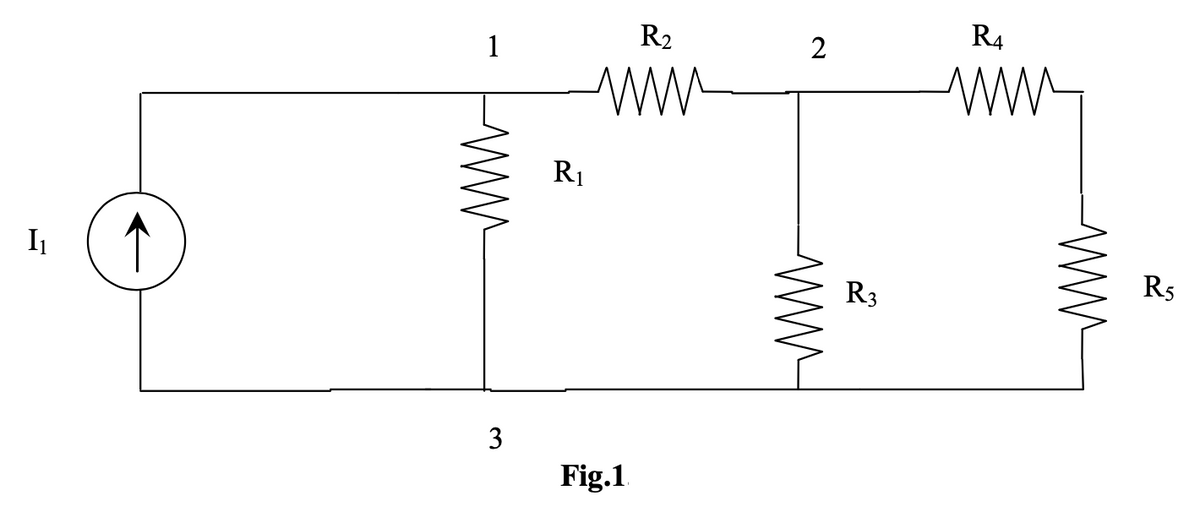
In the circuit shown in Fig. 1, node 3 is assumed as the reference node. The voltage at node 1 is the voltage at that node with respect to node 3. Similarly, the voltage at node 2 is the voltage at that node with respect to node 3.

                                       Electrical Engineering homework question answer, step 1, image 2

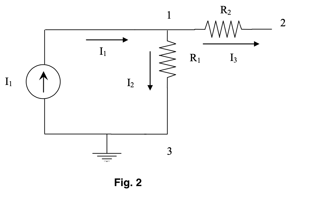
Applying KCL at node 1 ; the current entering is equal to the current leaving (refer Fig. 2)

                                     Electrical Engineering homework question answer, step 1, image 3

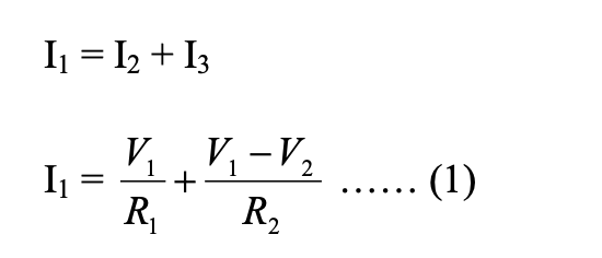
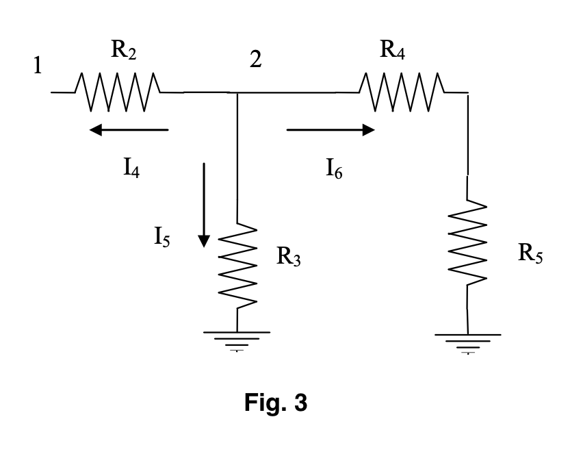
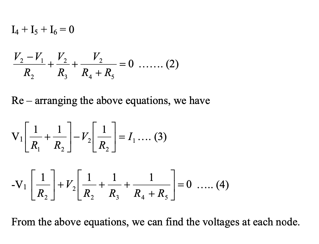
Where V1 and V2 are the voltages at node 1 and 2, respectively. Similarly, at node2, the current entering is

equal to the current leaving as shown in Fig. 3.

                                             Electrical Engineering homework question answer, step 1, image 4

                             Electrical Engineering homework question answer, step 1, image 5


trending now

Trending now

This is a popular solution!

steps

Step by step

Solved in 2 steps with 7 images

Blurred answer
Knowledge Booster
Superposition theorem
Learn more about
Need a deep-dive on the concept behind this application? Look no further. Learn more about this topic, electrical-engineering and related others by exploring similar questions and additional content below.
Similar questions
  • SEE MORE QUESTIONS
Recommended textbooks for you
Delmar's Standard Textbook Of Electricity
Electrical Engineering
ISBN:
9781337900348
Author:
Stephen L. Herman
Publisher:
Cengage Learning
Power System Analysis and Design (MindTap Course …
Electrical Engineering
ISBN:
9781305632134
Author:
J. Duncan Glover, Thomas Overbye, Mulukutla S. Sarma
Publisher:
Cengage Learning