
Introductory Circuit Analysis (13th Edition)
13th Edition
ISBN: 9780133923605
Author: Robert L. Boylestad
Publisher: PEARSON
expand_more
expand_more
format_list_bulleted
Related questions
Concept explainers
Question
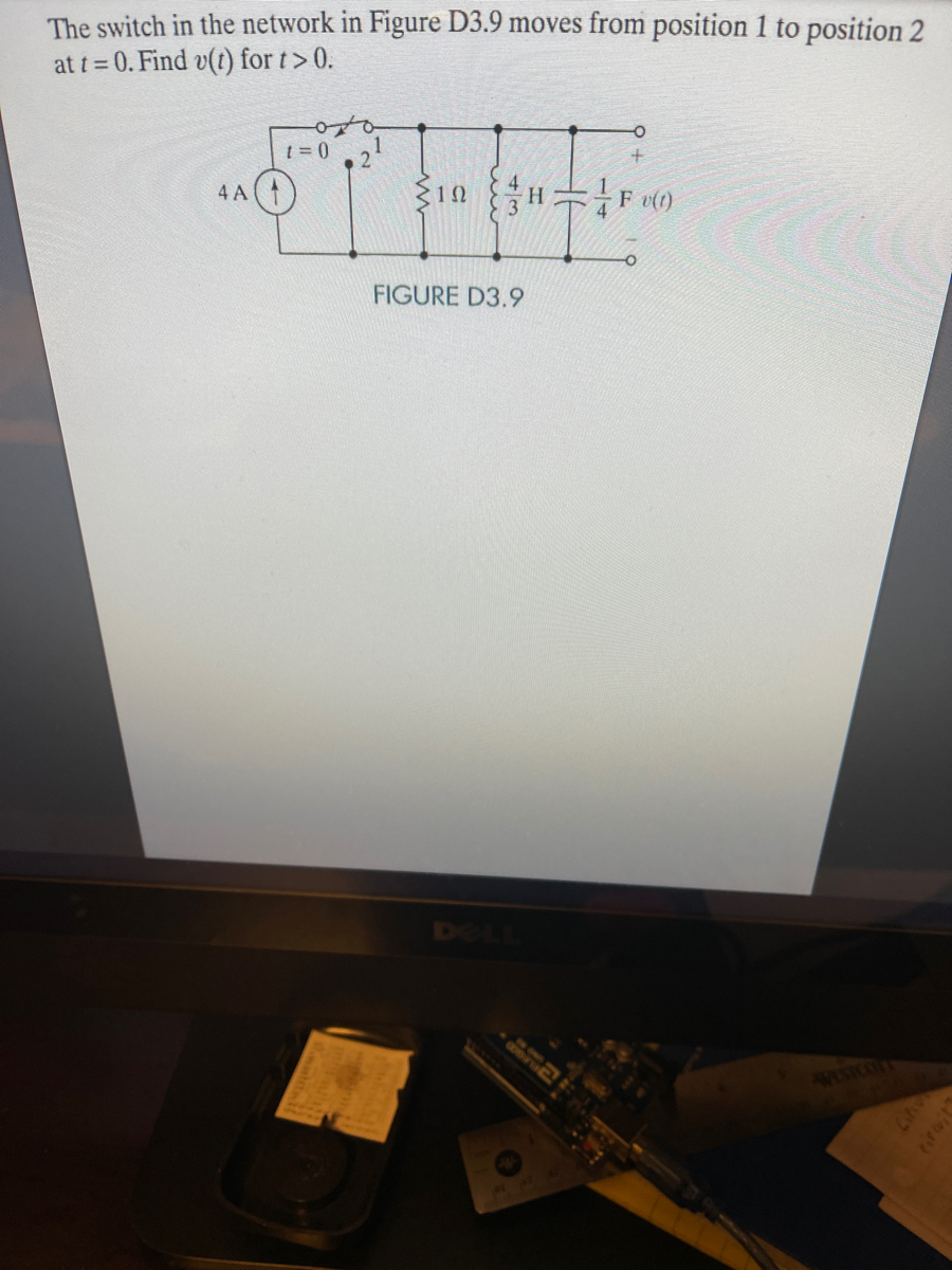

Transcribed Image Text:The switch in the network in Figure D3.9 moves from position 1 to position 2
at t = 0. Find v(t) for t> 0.
1 = 0
4 A
v(1)
FIGURE D3.9
61
WISTCOFTY
CN
Expert Solution
This question has been solved!
Explore an expertly crafted, step-by-step solution for a thorough understanding of key concepts.

This is a popular solution

Trending nowThis is a popular solution!

Step by stepSolved in 2 steps with 3 images

Knowledge Booster


Learn more about
Need a deep-dive on the concept behind this application? Look no further. Learn more about this topic, electrical-engineering and related others by exploring similar questions and additional content below.Similar questions
- write a description of the circuit function, Circuit diagram.arrow_forward(d) For the circuit shown in Figure Q1(d), the inductors have the following value: L1 = 1 mH, L2 = L3 = 2 mH, L4 = 5 mH, and L5 = L6 = 4 mH. Calculate the total inductance as seen from: (i) Terminals a-b (ii) Terminals b-carrow_forwardConsider the circuit shown below. R1 = 100 N R2 = 100 N C1 10 mF V = 12 V R3 3 100 N C, = 4.7 mF %3D %3D a. After the switch has been closed for a very long time, what are the voltages across the capacitors C1 and C2? Hint for (a) Voltage across C1 is V, and voltage across C2 is V. b. After the switch has been closed for a very long time, what is the energy stored in each capacitor? Hint for (b) Energy stored on C, is J, and energy stored on C, is J.arrow_forward
- Using a single 7400 IC, construct a circuit to output the following Boolean function: F = A B + C Darrow_forwardR3-50 Q UTM b) Figure Q4(b) is referred. By using nodal analysis, solve for: 5 UTM i) the values of voltage V, and V; in 5 UTM & UTM ii) the values of current, Ij in phasor domain and time domain UTM MS UTM 5 UTS 5 UTM 5 UTM 5 UTM & UTM 8 UTM 8 UTM 8 UTM 5 UTM 8 UTM 8 UTM R=10 Q UTM & UTM 8 UTM 8 UTM 8 U U XL=j5 Q 8 UTMSN 10020° v A 5 UTM 6 UTM R-20 Q R;=10 Q UTM 5 UTM M 8 UTM JUTM 8 UT 8 UTM 5 UM 8 UTM 5 UTM UTM UTM 8 UTM I-520° A UTM TM 8 UTM UTM 5 UTarrow_forwardAn RTD forms one arm of a Wheatstone bridge, as shown in the figure below and the RTD is used to measure a constant temperature with the bridge operated in deflection mode. The bridge is balanced when the RTD temperature is at 0°C and the resistance R1 is set to 20 N. The RTD has a resistance of 20 2 at 0°C with an a = 0.0045°C-1. If the RTD is subjected to a temperature of 120°C and the output voltage from the bridge is 1.2 Volts, what is the input voltage? R₂ R₁ E₁ Hilllo R3 RTD RRTDarrow_forward
- 1.Utilize an appropriate R-C circuit powered by a 120 V DC source. This RC circuit will be the energy source to power a single Neon Lamp. 2. Neon and other gas-based lamps often require a threshold voltage before they turn "on", i.e. emit light. The neon lamp you will use has a turn-on voltage of 70 V. In the provided LTspice model of such a neon lamp, you can explore how this light turns on and off (i.e. the current through the lamp is high when the lamp is on), when it is powered by a pulsed voltage source. Play around with the pulsed source parameters to investigate the lamp's behavior. However, keep the lamps LIspice parameters fixed (i.e. do not change the attributes of the lamp). 3. Using the RC circuit Power your Neon Lamp so that it turns on every 0.1 seconds (10 Hz frequency). The time for which it remains on is not critical, but should obviously be much less than 0.1 seconds.arrow_forwardAsap pleasearrow_forwardConvert the following problem to standard form and solve. Maximize x1 + 4x2 + X3 Subject to 2x1 – 2x2 + X3 = 4 x1 – x3 = 1 x2 2 0, x3 > 3.arrow_forward
- Please in typing format please ASAP for the Please I will like it please ASAP for thearrow_forwardSimplify the following block diagram as much as possible, using the algebra rules for block diagrams. .. .arrow_forwardThis is a practice question from my Introduction to Circuits course. What is the process for solving this? Thank you for your assistance.arrow_forward
arrow_back_ios
SEE MORE QUESTIONS
arrow_forward_ios
Recommended textbooks for you
- Introductory Circuit Analysis (13th Edition)Electrical EngineeringISBN:9780133923605Author:Robert L. BoylestadPublisher:PEARSON
 Delmar's Standard Textbook Of ElectricityElectrical EngineeringISBN:9781337900348Author:Stephen L. HermanPublisher:Cengage Learning
 Programmable Logic ControllersElectrical EngineeringISBN:9780073373843Author:Frank D. PetruzellaPublisher:McGraw-Hill Education
  Fundamentals of Electric CircuitsElectrical EngineeringISBN:9780078028229Author:Charles K Alexander, Matthew SadikuPublisher:McGraw-Hill Education
 Electric Circuits. (11th Edition)Electrical EngineeringISBN:9780134746968Author:James W. Nilsson, Susan RiedelPublisher:PEARSON
 Engineering ElectromagneticsElectrical EngineeringISBN:9780078028151Author:Hayt, William H. (william Hart), Jr, BUCK, John A.Publisher:Mcgraw-hill Education,
Introductory Circuit Analysis (13th Edition)
Electrical Engineering
ISBN:9780133923605
Author:Robert L. Boylestad
Publisher:PEARSON
Delmar's Standard Textbook Of Electricity
Electrical Engineering
ISBN:9781337900348
Author:Stephen L. Herman
Publisher:Cengage Learning
Programmable Logic Controllers
Electrical Engineering
ISBN:9780073373843
Author:Frank D. Petruzella
Publisher:McGraw-Hill Education
Fundamentals of Electric Circuits
Electrical Engineering
ISBN:9780078028229
Author:Charles K Alexander, Matthew Sadiku
Publisher:McGraw-Hill Education
Electric Circuits. (11th Edition)
Electrical Engineering
ISBN:9780134746968
Author:James W. Nilsson, Susan Riedel
Publisher:PEARSON
Engineering Electromagnetics
Electrical Engineering
ISBN:9780078028151
Author:Hayt, William H. (william Hart), Jr, BUCK, John A.
Publisher:Mcgraw-hill Education,