
Elements Of Electromagnetics
7th Edition
ISBN: 9780190698614
Author: Sadiku, Matthew N. O.
Publisher: Oxford University Press
expand_more
expand_more
format_list_bulleted
Related questions
Concept explainers
Question

Transcribed Image Text:**Problem Statement:**
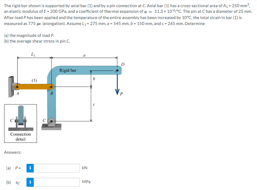
The rigid bar shown is supported by axial bar (1) and by a pin connection at C. Axial bar (1) has a cross-sectional area of \( A_1 = 250 \, \text{mm}^2 \), an elastic modulus of \( E = 200 \, \text{GPa} \), and a coefficient of thermal expansion of \( \alpha = 11.3 \times 10^{-6} / ^{\circ} \text{C} \). The pin at C has a diameter of 25 mm. After load P has been applied and the temperature of the entire assembly has been increased by \( 10^{\circ} \text{C} \), the total strain in bar (1) is measured as \( 775 \, \mu \epsilon \) (elongation). Assume \( L_1 = 275 \, \text{mm} \), \( a = 545 \, \text{mm} \), \( b = 150 \, \text{mm} \), and \( c = 265 \, \text{mm} \). Determine:
(a) the magnitude of load P.
(b) the average shear stress in pin C.
**Diagram Description:**
The diagram features a rigid bar supported vertically at point D by a load \( P \), and horizontally by an axial bar (1) at point B. There is a pin connection at point C, holding the base of a hinge that connects to the rigid bar. The section from A to B represents bar (1) that extends horizontally and then bends to attach vertically with the rigid bar at point B.
**Dimensions Provided:**
- \( L_1 \) (distance from A to B): 275 mm
- \( a \) (distance from C to D): 545 mm
- \( b \) (distance from B to D): 150 mm
- \( c \) (distance from C to B): 265 mm
**Answers Section:**
\( \begin{array}{cc}
(a) & P = \quad \_ \_ \_ \_ \quad \text{kN} \\
(b) & \tau_C = \quad \_ \_ \_ \_ \quad \text{MPa} \\
\end{array} \)
**Detail Mentioned:**
- The cross-sectional view of the pinned connection
Expert Solution
This question has been solved!
Explore an expertly crafted, step-by-step solution for a thorough understanding of key concepts.

Step by stepSolved in 3 steps with 23 images

Knowledge Booster


Learn more about
Need a deep-dive on the concept behind this application? Look no further. Learn more about this topic, mechanical-engineering and related others by exploring similar questions and additional content below.Similar questions
- Please answer to the best of your ability. Please show all necesary work and answersarrow_forward7 ft 5 ft The assembly shown above includes column AB, which has the following properties: Pinned (top and bottom) for buckling about x-axis Free at top and fixed at bottom for buckling about y-axis Circular cross-section with 8-inch diameter E = 10000 ksi Which of the following is closest to the critical buckling force of column AB? O Per = 269 kip O Per = 1080 kip O Per = 538 kip O Per = 135 kiparrow_forwardProblem 7 The shear stress-strain diagram for an alloy is shown in the figure. If a bolt having a diameter of 0.25 in. is made of this material and used in the lap joint, determine the modulus of elasticity E and the force P required to cause the material to yield. Take v=0.3. 7 (ksi) Ty= 50 0.004 y (rad)arrow_forward
- Please show the formula used and free body diagram A rectangular steel block is 4 inches long in the x direction, 3 inches long in the y direction, and 4 inches long in the z direction. The block is subjected to a triaxial loading of three uniformly distributed forces as follows: 48 kips tension in the x direction, 60 kips compression in the y direction, and 54 kips tension in the z direction. If ν = 0.30 and E = 29 × 106 psi, determine the single uniformly distributed load in the x direction that would produce the same deformation in the y direction as the original loading.arrow_forwardA steel torsion bar AB with diameter d = 34 mm, and ductile material of tensile yield strength Sy = 276 MPa is attached to a rigid arm at A, supported by a bearing at C, and fixed at B, as the picture shows. At the right end of the arm is mounted the wheel on which the vertical force P acts from the ground and which passes through the center of the wheel. If bearing C acts as a simple support and the effect of transverse shear due to P is negligible, determine the maximum force P (in kN) that can be applied to the wheel. Consider a factor of safety n = 2.5. Use the maximum energy of distortion failure criterion and do the analysis on bar AB (torsion bar) in the section where the bearing is.arrow_forward
arrow_back_ios
arrow_forward_ios
Recommended textbooks for you
- Elements Of ElectromagneticsMechanical EngineeringISBN:9780190698614Author:Sadiku, Matthew N. O.Publisher:Oxford University Press
 Mechanics of Materials (10th Edition)Mechanical EngineeringISBN:9780134319650Author:Russell C. HibbelerPublisher:PEARSON
 Thermodynamics: An Engineering ApproachMechanical EngineeringISBN:9781259822674Author:Yunus A. Cengel Dr., Michael A. BolesPublisher:McGraw-Hill Education
  Control Systems EngineeringMechanical EngineeringISBN:9781118170519Author:Norman S. NisePublisher:WILEY
 Mechanics of Materials (MindTap Course List)Mechanical EngineeringISBN:9781337093347Author:Barry J. Goodno, James M. GerePublisher:Cengage Learning
 Engineering Mechanics: StaticsMechanical EngineeringISBN:9781118807330Author:James L. Meriam, L. G. Kraige, J. N. BoltonPublisher:WILEY
Elements Of Electromagnetics
Mechanical Engineering
ISBN:9780190698614
Author:Sadiku, Matthew N. O.
Publisher:Oxford University Press
Mechanics of Materials (10th Edition)
Mechanical Engineering
ISBN:9780134319650
Author:Russell C. Hibbeler
Publisher:PEARSON
Thermodynamics: An Engineering Approach
Mechanical Engineering
ISBN:9781259822674
Author:Yunus A. Cengel Dr., Michael A. Boles
Publisher:McGraw-Hill Education
Control Systems Engineering
Mechanical Engineering
ISBN:9781118170519
Author:Norman S. Nise
Publisher:WILEY
Mechanics of Materials (MindTap Course List)
Mechanical Engineering
ISBN:9781337093347
Author:Barry J. Goodno, James M. Gere
Publisher:Cengage Learning
Engineering Mechanics: Statics
Mechanical Engineering
ISBN:9781118807330
Author:James L. Meriam, L. G. Kraige, J. N. Bolton
Publisher:WILEY