The LCR circuit in the Figure is driven by a voltage source with VAC = Vmax sin(2пft), where Vmax = 5 V, R = 130 £2, and C (a) If the resonant frequency is fres = 20 MHz, what is L? Submit Answer Tries 0/8 (b) What is the amplitude (the peak value) of the current when f = fres? Submit Answer Tries 0/8 = 30 nF. VAC R www m L C
Q: Graph the Vo vs. V, (show the slopes of the lines). Assume the Zener diode to be ideal with a V-4V,…
A: In the given questions we need to draw the transfer characteristics of the given system.
Q: Three charged particles are located at the corners of an equilateral triangle as shown in the figure…
A:
Q: Consider the circuit below: 1200:2400 34j Ω I 1200 30° V -10j Ω 50 Ω 100 Ω -3j Ω The transformer…
A:
Q: An electrical water boiler is used for supplying steam to the process in a food industry. The rating…
A: Step 1: Initial InvestmentInitial Investment=Cost of New Boiler+ Erection and Commissioning…
Q: find the truth table for this circuit , thank you in advance
A: The given logic circuit isWe need to determine the truth table for the logic circuit.
Q: Please show how it would look on that graph please use the given graph
A: Given minterms are Given graph is,Asked to show how it would look on that graph.
Q: 7.5 A wave radiated by a source in air is incident upon a soil surface, whereupon a part of the wave…
A: Question is low less medium
Q: Vi RB Vcc Rc our A BJT (B=200) is implemented in an amplifier circuit, with a VCC of 15 volts. One…
A: The objective of the question is to determine the value of the base resistance (RB) in a Bipolar…
Q: Can you solve the remaining 2to4 they are 3 questions only and as I remember you can answer upto 3…
A: Since you have posted multiple (metioned 2 to 4) questions, we will provide the solution only to the…
Q: Question 7: Three capacitors having capacitances 20 μF, 30 uF and 40 μF are connected in series with…
A: The given data is shown below
Q: 1.4
A: The voltage obtained is: VL(t)=−s900mVe(−s300t) Note the final value depends upon the value of…
Q: what is the DTFT of sin(n)/n
A:
Q: 9. Find Io 12/0°V 102 ww 2/0° A 1Ω 1Ω
A: Given circuit is, Asked to find the current Io =?
Q: 2.7
A: Ans. The 2€ coins are larger then the 1€ coins.Explanation:
Q: The steady-state voltage drop between the load and the sending end of the line seen in (Figure 1) is…
A: The given circuit diagram is shown below,
Q: Finish the timing diagrams of the latches and flipflops.
A: using the characteristic equations and gate or clock pulse whichever applicable , i have made the…
Q: For the network shown below, composed of standard values: a) Find the mathematical expressions for…
A: The given circuit isWe need to determine a. The mathematical expressions for the voltage vC and the…
Q: In the op-amp circuit given in the figure, the load current iL is
A: The given data is shown below:
Q: 5. 4.5 Design a combinational circuit with three inputs x, y, and z and three outputs A, B, and C.…
A:
Q: It is possible to convert the circuit on the left to that on the right so that any element connected…
A: For the given source transformation circuit the validity of the given statements needs to be…
Q: A dc power supply has a no-load voltage of 30 V, and a full-load voltage of 25 V at a full-load…
A: As the given data is,No load voltage is 30V.Full load voltage is 25V.Full load current is 1A.As we…
Q: Needs Complete typed solution with 100 % accuracy.
A: The objective of this question is to determine the readings on an ideal ammeter and voltmeter in a…
Q: The current in an RLC circuit is described by d² + 10 + 25 i = 0 If (0) = 12 A and di(0)/dt = 0,…
A: It is asked to solve the given differential equation representing the current in RLC circuit
Q: Consider the circuit shown in figure 3. Use Kirchhoff's voltage law to derive a differential…
A: In the given questions we need to derive the differential equations and calculate the phase…
Q: Several steps are required to find the thevenin voltage and resistance for a linear two-terminal…
A: A linear two terminal circuit is connected to a load as shown belowThe Thevenin's equivalent circuit…
Q: Find V0 please answer in typing format solution
A: In the given circuit the value of the unknown voltage needs to be calculated. The voltage can be…
Q: 4-A single phase transformer has maximum efficiency at 75% of full load. Its copper loss at full…
A:
Q: 5. In a three-phase circuit, if a fuse is lost and voltage is lost in phase 1, what must be true…
A: 5. In a three-phase circuit, if a fuse is lost and voltage is lost in phase 1, what must be true…
Q: Design a full adder using two half-adders.
A: In the given question we need to calculate the full adder using half adder .
Q: For the circuit shown in the figure, determine the impedance Zin seen by the source when R1 = 4.6 Ω.…
A: The circuit diagram,
Q: a) Draw the pneumatic circuit of the system b) Built and run the pneumatic circuit in your FESTO
A: Given parameters the gates is to be opened or closed by means of 4 pushtwo being inside and two…
Q: Consider a lossless transmission line of length 1 = 0.62 with a characteristic impedance Zo=50 Q2…
A:
Q: Consider the control system shown below. G₁(S) R(s) 2 Y(s) K (s + 1) s(s+4) 3 (s²+2s+5) Find: Gp(s)…
A: Given:a control system,we need to find the Gp(s) so that the steady state error for step input is 0.
Q: VIÐ) R₁ www R3 R2 C₁ Ry HH L₁ чи R5 ww 42 ง m чи www L C3
A:
Q: B + จง R www чи Vout (+)
A:
Q: 1. Hill Given the following circuit: R1 w 3Ω V1 12 V ·ទ 5Ω R2 w R3 4Ω Determine: a. R1, R2, R3, IR4,…
A: The circuit diagram,
Q: H.W1: Find the 3-bit PCM signal for the message wave and sampling signal that shown below.
A: According to the question, for the given message waveform and sampling signal as shown belowWe need…
Q: For the circuit below if the switch is closed for t0 find the following: 40 Ω ти + 10 Ω www 25 μF…
A: Giiven here a circuit and asked to find voltage and time constant.
Q: * 7.3 The electric field phasor of a uniform plane wave is given by E = ŷ 10ej0.2z (V/m). If the…
A:
Q: Solve the following circuit for I. using. Nodal Analysis. 212 w HV F ΙΚΩ ↑ 12 MA ↓。
A: Given:we need to determine the current I0 using nodal analysis.
Q: Sketch the output voltage (v.) and the transfer characteristics (v. against v;) for each circuit of…
A: Since you have posted the questions with multiple subparts. So we are supposed to answer 3…
Q: Required information Consider the given four-bit R-2R ladder DAC. 2R 2R V₂oww 2R V30 ww R 2R ww 2R R…
A: The given 4bit R-2R ladder DACVoltage Use superposistion to determine the contribution of each input…
Q: Sometimes "bubbles" are used to indicate inverters on the input lines to a gate. What are the…
A: In the given questions we need to calculate the equivalent logic gate of the given logic circuit.
Q: a/write the nodal equations for the Network showing 10 2 452 j4 eeeeeex 10 Loo 00000 10130° -js 36 9…
A: The circuit diagram,
Q: Determine the transfer function of the systems whose input-output behavior is shown below (It is not…
A: The input-output plots of two systems are given. It is asked to determine the transfer function of…
Q: (a) Determine the I-V characteristics equation at terminals a-b. Draw the approximate graph from the…
A: Given circuit is,Asked to determine the I V characteristics of the above circuit,Draw the simplest…
Q: Show that AB + ABC + BC = AC + BC
A: The given data is shown below:
Q: Urgent!! Please write down all workings thank you! Answer: V1 = 0.928cos (10t - 86.142deg) mV V2…
A: V1 = 0.928cos (10t - 86.142deg) V V2 = 0.969cos (10t - 16.48deg) VI1 = 2.5 cos 10t mA I2 =…
Q: Given that Vs = 3 V, R₁ = 12, and R₂ = 30, what is the maximum current Is for which the current…
A:
Q: Derive the Transfer Function of the following RC and RLC circuits: (Hint: Solve directly in the…
A: Given:a circuit,we need to derive transfer function assuming zero initial conditions.
Needs Complete typed solution with 100 % accuracy.
Don't use chat gpt or ai i definitely upvote you.
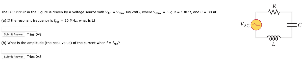
Unlock instant AI solutions
Tap the button
to generate a solution
Click the button to generate
a solution
- A coil of resistance 25 Ω and inductance 100 mH is connected in series with acapacitance of 0.12 μF across a 200 V, variable frequency supply. Calculate (a)the resonant frequency, (b) the current at resonance, and (c) the factor bywhich the voltage across the reactance is greater than the supply voltage.3. A series circuit consists of a 30-ohm resistor. a 0.104-henrv inductor, and a 40-microFarad capacitor. If a vanable frequencv I2U-volt source is connected across its terminals, (a) calculate the resonant frequency. fOr the condition of resonance, determine (b) the circuit current and power; (C) the voltage drops across the resistor, the inductor, and the capacitor Prepared bv ENGR. JEFFSON S. BALDEMECACritically analyse the principles of circuit theory to explain series resonant circuit. Deriveexpression for resonant frequency and evaluate the resonant frequency and current flowing atresonance in a series a.c circuit consisting of a coil of resistance 4 ohm , inductance 70mH and capacitance0.06 uF if the supply voltage is 100V
- A coil of inductance 0.20H and resistance 60 ohm is connected in parallel with a 20μF capacitor across a 20V, variable frequency supply. Calculate (a) the resonant frequency, (b) the dynamic resistance, (c) the current at resonance and (d) the circuit Q-factor at resonance.Compute the impedance Z of a series R-L-C circuit at angular frequencies ω = (a) 1001 rad/s Assume R = 201 Ω, L = 0.902 H and C = 2.01 μF. (b) What is the resonant angular frequency ωRES of the circuit? Assume the voltage source amplitude is Vm = 100.00 (V). (c) What is the current amplitude Im when the circuit is at the resonant angular frequency? (d) What is the current amplitude Im when the circuit is at 751 rad/s? (e) Should the answers to (c) and (d) be nearly equal? Explain.A coil of resistance 25Ω and inductance 100mH is connected in series with a capacitance of 0.12μF across a 200V, variable frequency supply. Calculate: i. The resonant frequency. ii. The current at resonance. iii. The factor by which the voltage across the reactance is greater than the supply voltage.
- A circuit consisting of a coil of resistance 12 ohms and inductance 0.15 H in series with a capacitor of 12 micro Farad is connected to a variable frequency supply which has a constant voltage of 24 Volts. Calculate (a) the resonant frequency (b) the current in the circuit at resonance (c) the voltage across the capacitor and the coil at resonance.A circuit comprises of a coil (resistance of 20W, inductance of 600mH), and a capacitor of 2.0mF connected in parallel. A supply of 80V at 50 Hz is connected across the circuit. Calculate: Impedance Phase angle Resonant frequency Q-factor Bandwidth How does each of the above parameters change if the components are connected in series? Explain what is happening to both parallel and series connections of the above circuit at resonant frequency and critically evaluate the effects on circuit currents, voltages and components.A coil of resistance 20 Q and inductance of 300 mH is connected in parallel with a capacitance of 200 uF. The combination is connected across 200 V, variable frequency power supply. At what frequency will the parallel circuit resonate and what would be the current at resonance? [Ans 19.26 Hz, 0.431 A]
- For the parallel RLC circuit given in Figure 5 for Vs=10sinωt R=2.2 Ω, L=100 µH andC=1000 µFa) Obtain the resonant frequency ω0, the quality factor Q and the bandwidth B.b) Calculate the half-power frequencies ω1 and ω2.c) Determine the power consumption at ω0, ω1, and ω2.d) Plot the current amplitude versus frequencye) Use LTSPICE to plot frequency response.A 15.9 uF capacitor and a 15.1 mH inductor are connected in parallel. In series with these units are a variable resistor R and an adjustable reactive device X, joined in series. (a) Determine the kind and size of device X (inductance in Henrys or capacitance in uF) when the circuit is connected to a 50 volt 200 cps source and is adjusted to resonance. (b) For the resonant condition, calculate the value of R if the voltage drop across the paralleled units is to be 100 volts -write legibly and show complete solutionA 15.9 uF capacitor and a 15.1 mH inductor are connected in parallel. In series with these units are a variable resistor R and an adjustable reactive device X, joined in series. (a) Determine the kind and size of device X (inductance in Henrys or capacitance in uF) when the circuit is connected to a 50 volt 200 cps source and is adjusted to resonance. (b) For the resonant condition, calculate the value of R if the voltage drop across the paralleled units is to be 100 volts