Introductory Circuit Analysis (13th Edition)
13th Edition
ISBN: 9780133923605
Author: Robert L. Boylestad
Publisher: PEARSON
expand_more
expand_more
format_list_bulleted
Concept explainers
Question
Please solution to this assignment

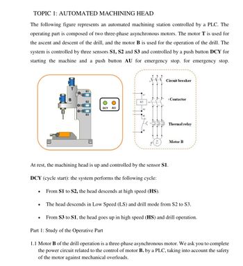
Transcribed Image Text:TOPIC 1: AUTOMATED MACHINING HEAD
The following figure represents an automated machining station controlled by a PLC. The
operating part is composed of two three-phase asynchronous motors. The motor T is used for
the ascent and descent of the drill, and the motor B is used for the operation of the drill. The
system is controlled by three sensors S1, S2 and S3 and controlled by a push button DCY for
starting the machine and a push button AU for emergency stop. for emergency stop.
Circuit breaker
S1
B
Contactor
S2
K1
DCY AU
Myy
ME
Thermal relay
Motor B
At rest, the machining head is up and controlled by the sensor $1.
DCY (cycle start): the system performs the following cycle:
From S1 to S2, the head descends at high speed (HS).
The head descends in Low Speed (LS) and drill mode from S2 to S3.
●
From $3 to S1, the head goes up in high speed (HS) and drill operation.
Part 1: Study of the Operative Part
1.1 Motor B of the drill operation is a three-phase asynchronous motor. We ask you to complete
the power circuit related to the control of motor B. by a PLC, taking into account the safety
of the motor against mechanical overloads.
20
Expert Solution
This question has been solved!
Explore an expertly crafted, step-by-step solution for a thorough understanding of key concepts.
Step by stepSolved in 3 steps with 1 images

Knowledge Booster
Learn more about
Need a deep-dive on the concept behind this application? Look no further. Learn more about this topic, electrical-engineering and related others by exploring similar questions and additional content below.Similar questions
- The student engineer of a campus radio station wishes to verify the effectiveness of the lightning rod on the antenna mast (see the figure below). The unknown resistance Ry is between points C and E. Point E is a "true ground," but is inaccessible for direct measurement because the stratum in which it is located is several meters below Earth's surface. Two identical rods are driven into the ground at A and B, introducing an unknown resistance Ry. The procedure for finding the unknown resistance Rx is as follows. Measure resistance Ry between points A and B. Then connect A and B with a heavy conducting wire and measure resistance R, between points A and C.arrow_forwardPlease click on pic to open itarrow_forwardA5arrow_forward
arrow_back_ios
arrow_forward_ios
Recommended textbooks for you
 Introductory Circuit Analysis (13th Edition)Electrical EngineeringISBN:9780133923605Author:Robert L. BoylestadPublisher:PEARSON
 Delmar's Standard Textbook Of ElectricityElectrical EngineeringISBN:9781337900348Author:Stephen L. HermanPublisher:Cengage Learning
 Programmable Logic ControllersElectrical EngineeringISBN:9780073373843Author:Frank D. PetruzellaPublisher:McGraw-Hill Education
 Fundamentals of Electric CircuitsElectrical EngineeringISBN:9780078028229Author:Charles K Alexander, Matthew SadikuPublisher:McGraw-Hill Education
 Electric Circuits. (11th Edition)Electrical EngineeringISBN:9780134746968Author:James W. Nilsson, Susan RiedelPublisher:PEARSON
 Engineering ElectromagneticsElectrical EngineeringISBN:9780078028151Author:Hayt, William H. (william Hart), Jr, BUCK, John A.Publisher:Mcgraw-hill Education,

Introductory Circuit Analysis (13th Edition)
Electrical Engineering
ISBN:9780133923605
Author:Robert L. Boylestad
Publisher:PEARSON

Delmar's Standard Textbook Of Electricity
Electrical Engineering
ISBN:9781337900348
Author:Stephen L. Herman
Publisher:Cengage Learning

Programmable Logic Controllers
Electrical Engineering
ISBN:9780073373843
Author:Frank D. Petruzella
Publisher:McGraw-Hill Education

Fundamentals of Electric Circuits
Electrical Engineering
ISBN:9780078028229
Author:Charles K Alexander, Matthew Sadiku
Publisher:McGraw-Hill Education

Electric Circuits. (11th Edition)
Electrical Engineering
ISBN:9780134746968
Author:James W. Nilsson, Susan Riedel
Publisher:PEARSON

Engineering Electromagnetics
Electrical Engineering
ISBN:9780078028151
Author:Hayt, William H. (william Hart), Jr, BUCK, John A.
Publisher:Mcgraw-hill Education,