
Introductory Circuit Analysis (13th Edition)
13th Edition
ISBN: 9780133923605
Author: Robert L. Boylestad
Publisher: PEARSON
expand_more
expand_more
format_list_bulleted
Related questions
Question
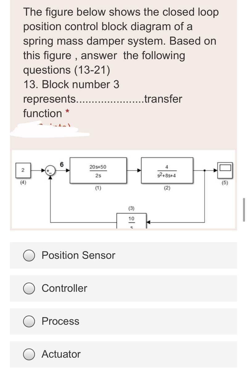

Transcribed Image Text:The figure below shows the closed loop
position control block diagram of a
spring mass damper system. Based on
this figure , answer the following
questions (13-21)
13. Block number 3
represents.. .
function *
...transfer
6
20s+50
2
2s
$2+8s+4
(4)
(5)
(1)
(2)
(3)
10
Position Sensor
Controller
Process
O Actuator
Expert Solution
This question has been solved!
Explore an expertly crafted, step-by-step solution for a thorough understanding of key concepts.

This is a popular solution

Trending nowThis is a popular solution!

Step by stepSolved in 2 steps with 2 images

Knowledge Booster


Learn more about
Need a deep-dive on the concept behind this application? Look no further. Learn more about this topic, electrical-engineering and related others by exploring similar questions and additional content below.Similar questions
- Using a labelled diagram, describe cold-junction compensation for athermocouple and explain why it is necessary. Describe cold-junctioncompensation using a temperature reference unit. Outline practicablemethods for compensation on industrial plant including electronic andsoftware compensation. State the advantages and disadvantages of thevarious techniques.arrow_forward4- What is the effect of adding capacitor in parallel to the load at the rectifier output? Note: Please do not handwritten.arrow_forwardA/D CONVERTER( NEED NEAT EXPLANATION HANDWRITTEN SOLUTION ONLY PLEASE OTHERWISE DOWNVOTE).arrow_forward
- 5arrow_forwardA 555 timer configured to run as an astable mode oscillator is shown in Figure 1. If the output is needed to have 30% duty cycle, i) Determine the required value of Rị if R2 = 7kN. ii) Determine the frequency of the output. iii) Draw the charging and discharging phase of capacitor Cext and its relation with the output waveform. ASsume Vcc = 12 V. +Vcc (4) |(8) R1 RESET Vcc (7) DISCH 555 D1 R2 (6) THRESH (3) OUT (2) TRIG (5) CONT GND :Cext 0.01 µF (1) 0.01µF Figure 1arrow_forward3) Explain the construction, principle of operation, circuit and applications of Variable reluctance transducer with neat diagrams. 4) Describe the construction of LVDT and explain its principle of operation with the aid of diagram, list the advantages, disadvantages and applications of LVDT.arrow_forward
- a. What are DC Choppers? Explain what TRC (Time Ratio Control) is b. A Buck Converter is used with a 2mH inductor and a supply voltage of 15V. The load resistance is maintained at 1 Q. The switching frequency is 100 kHz. i. Determine the duty cycle needed for an output voltage of 5V. ii. Calculate the output supply voltage ripple. iii. What are the consequences of decreasing the load resistance by 50% (to 0.5 ohms)? c. Identify the class of converter in the figure and describe the principle of operation of such a converter. d. State a possible application of such a converter. e. Draw the output waveforms of the current and voltage and the gate pulses of the choppers. Indicate on the current waveform the region of operation of the choppers and diodes. CH₁ CH₂ AD₂ Chopper wwwroo E +← Voarrow_forwardAnálisis de rectificador onda completa Consider the capacitor-filter rectifier circuit as shown in Figure 1. The input is a single-phase source that is derived from a 220 Vrms mains. Tasks for analysis: (a) Rig up the circuit as shown in Figure land plot V andi versus time. (b) Why is there ringing on the current wave-form? (c) What is the series impedance of the circuitệ (d) Plot V and V. versus time. What is the ripple? How does ripple depend on load, capacitor C; and frequency of input wave-form? (e) Measure the current and voltage waveform across the rectifier diode. (f) Estimate the average and ms currents through the rectifier diode, Calculate the diode power dissipation. (g) What should be the peak current rating of the diode? (h) Change the initial charge voltage on the capacitor Cr. What is the effect on the input surge current? (i) Change the phase angle of the input V, at start up. Observe the effect on current i. What happens and why? 1) Under whaf conditions do you get…arrow_forward
arrow_back_ios
arrow_forward_ios
Recommended textbooks for you
- Introductory Circuit Analysis (13th Edition)Electrical EngineeringISBN:9780133923605Author:Robert L. BoylestadPublisher:PEARSON
 Delmar's Standard Textbook Of ElectricityElectrical EngineeringISBN:9781337900348Author:Stephen L. HermanPublisher:Cengage Learning
 Programmable Logic ControllersElectrical EngineeringISBN:9780073373843Author:Frank D. PetruzellaPublisher:McGraw-Hill Education
  Fundamentals of Electric CircuitsElectrical EngineeringISBN:9780078028229Author:Charles K Alexander, Matthew SadikuPublisher:McGraw-Hill Education
 Electric Circuits. (11th Edition)Electrical EngineeringISBN:9780134746968Author:James W. Nilsson, Susan RiedelPublisher:PEARSON
 Engineering ElectromagneticsElectrical EngineeringISBN:9780078028151Author:Hayt, William H. (william Hart), Jr, BUCK, John A.Publisher:Mcgraw-hill Education,
Introductory Circuit Analysis (13th Edition)
Electrical Engineering
ISBN:9780133923605
Author:Robert L. Boylestad
Publisher:PEARSON
Delmar's Standard Textbook Of Electricity
Electrical Engineering
ISBN:9781337900348
Author:Stephen L. Herman
Publisher:Cengage Learning
Programmable Logic Controllers
Electrical Engineering
ISBN:9780073373843
Author:Frank D. Petruzella
Publisher:McGraw-Hill Education
Fundamentals of Electric Circuits
Electrical Engineering
ISBN:9780078028229
Author:Charles K Alexander, Matthew Sadiku
Publisher:McGraw-Hill Education
Electric Circuits. (11th Edition)
Electrical Engineering
ISBN:9780134746968
Author:James W. Nilsson, Susan Riedel
Publisher:PEARSON
Engineering Electromagnetics
Electrical Engineering
ISBN:9780078028151
Author:Hayt, William H. (william Hart), Jr, BUCK, John A.
Publisher:Mcgraw-hill Education,