Structural Analysis
6th Edition
ISBN: 9781337630931
Author: KASSIMALI, Aslam.
Publisher: Cengage,
expand_more
expand_more
format_list_bulleted
Concept explainers
Question

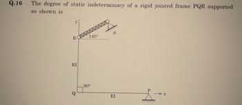
Transcribed Image Text:Q.16
The degree of static indeterminacy of a rigid jointed frame PQR supported
as shown is
R
EI
145°
90°
S
EI
P
X
Expert Solution
This question has been solved!
Explore an expertly crafted, step-by-step solution for a thorough understanding of key concepts.
Step by stepSolved in 2 steps

Knowledge Booster
Learn more about
Need a deep-dive on the concept behind this application? Look no further. Learn more about this topic, civil-engineering and related others by exploring similar questions and additional content below.Similar questions
- 6. A force P of magnitude 330 lb acts on the frame shown at point E. (a) Determine the rectangular representation of Force Vector P. (b) Determine the moment of P about point O. (c) Determine the moment of P about a line joining points 0 and D. 7.5 in. E 7.5 in 30 in H 10 in. 10 in.arrow_forwardDetermine the bending stress at point A of the beam using the result obtained in Prob. 6–106. The moments of inertia of the cross-sectional area about the z and y axes are Iz = Iy = 5.561 in4 and the product of inertia of the cross sectional area with respect to the z and y axes is Iyz = −3.267 in4arrow_forwardThe beam with cross-section shown in Figure 1 is subjected to a uniformly distributed load and a moment. The centroidal axis of the section is c= 74.44 mm from the bottom. I. -2.18x10 mm. E = 2.1×10 MPa. a) At a cross-section 2 m to the right of support A; i) ii) iii) Calculate the Shear Force, V, and the Bending Moment, M. Determine the maximum bending stress. Sketch the bending stress distribution across the section, include critical tension & compression stress values. Determine shear stress developed at the flange-web interface and also the shear stress at the neutral axis of the cross-section. Sketch the shear stress distribution across the section, include the critical values. b) Using the double integration method, find the deflection curve for 0≤x≤5 m. 3 kN/m 5m 3 m- Figure 1 15 kN-m 100 All dimensions are in mm.arrow_forward
- 15 kN/m 60 kN C A I B 21 10 m 5 m 5 m Figure no. 8arrow_forwardSolve the problem by the moment-area method. The beam has constant flexural rigidity EI. A simple beam AB supports two concentrated loads P at the positions shown in the figure. B C 4. 4 A support C at the midpoint of the beam is positioned at distance d below the beam before the loads are applied. Assuming that d = 12 mm, L = 5.4 m, E = 200 GPa, and I = 193 x 10° mm, calculate the magnitude of the loads P (in kN) so that the beam just touches the support at C. 163.87 x kNarrow_forwardFind the maximum angle of rotation for the shaft subjected to linearly %3D distributed torque. Tx) = kx,GJ constant. T(x)arrow_forward
arrow_back_ios
arrow_forward_ios
Recommended textbooks for you

 Structural Analysis (10th Edition)Civil EngineeringISBN:9780134610672Author:Russell C. HibbelerPublisher:PEARSON
 Principles of Foundation Engineering (MindTap Cou...Civil EngineeringISBN:9781337705028Author:Braja M. Das, Nagaratnam SivakuganPublisher:Cengage Learning
 Fundamentals of Structural AnalysisCivil EngineeringISBN:9780073398006Author:Kenneth M. Leet Emeritus, Chia-Ming Uang, Joel LanningPublisher:McGraw-Hill Education
 Traffic and Highway EngineeringCivil EngineeringISBN:9781305156241Author:Garber, Nicholas J.Publisher:Cengage Learning


Structural Analysis (10th Edition)
Civil Engineering
ISBN:9780134610672
Author:Russell C. Hibbeler
Publisher:PEARSON

Principles of Foundation Engineering (MindTap Cou...
Civil Engineering
ISBN:9781337705028
Author:Braja M. Das, Nagaratnam Sivakugan
Publisher:Cengage Learning

Fundamentals of Structural Analysis
Civil Engineering
ISBN:9780073398006
Author:Kenneth M. Leet Emeritus, Chia-Ming Uang, Joel Lanning
Publisher:McGraw-Hill Education


Traffic and Highway Engineering
Civil Engineering
ISBN:9781305156241
Author:Garber, Nicholas J.
Publisher:Cengage Learning