Structural Analysis
6th Edition
ISBN: 9781337630931
Author: KASSIMALI, Aslam.
Publisher: Cengage,
expand_more
expand_more
format_list_bulleted
Concept explainers
Question

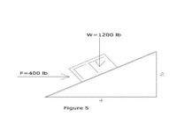
Transcribed Image Text:1. The body on the incline in Fig. 5 is subjected to the vertical and Horizontal Forces shown. Find the
components of each force along x-y axes oriented parallel and perpendicular to the incline.

Transcribed Image Text:w=1200 Ib
F-400 Ib
Figure 5
Expert Solution
This question has been solved!
Explore an expertly crafted, step-by-step solution for a thorough understanding of key concepts.
Step by stepSolved in 2 steps with 1 images

Knowledge Booster
Learn more about
Need a deep-dive on the concept behind this application? Look no further. Learn more about this topic, civil-engineering and related others by exploring similar questions and additional content below.Similar questions
- /٤١٢ 9.5. A curved beam is built up by welding together rectangular and elliptical cross-section curved beams; the cross section is shown in Fig. P9.5. The center of curvature is located 20 mm from B. The curved beam is subjected to a positive bending moment M.. Determine the stresses at points B and C in terms of M₂. 15 mm ↓ 30 mm 15 mm 30 mm 20 mm PROBLEMS 397arrow_forwardDetermine the magnitude and coordinate direction angles of the resultant force acting at A. Given that FB = 610 N and FC = 420 N .Determine the magnitude of the resultant force acting at A.Determine coordinate direction angle? 0.5 m 1m 1.5 m FB 2 m Fc 0.5 m 1.5 m 3.5 marrow_forwardProblem: Analyze the given indeterminate beam by computing the support reactions. Use the SLOPE- DEFLECTION EQUATION. Assume El to be constant throughout the entire span of the beam. 3 kN 2 m 3 kN/m 4 m 5 kN/m 6 marrow_forward
- 15 kN/m 60 kN C A I B 21 10 m 5 m 5 m Figure no. 8arrow_forwardGive me right solution with clear calculations step by steparrow_forwardLearning Goal: A beam with length L = 2.9 m is supported by a pin joint at A and a cable attached at C as shown in (Figure 1). It is subjected to the distributed load with w₁ =1.7 kN/m and w₂ = 2.1 kN/m. The angle between the cable and the beam is 0 = 35°. Determine the normal force, shear force, and bending moment acting at point B, located x = 0.6 m to the left of the end of the beam. D Wi W2 C B L Begin by finding the support reactions for the beam using the free-body diagram shown in (Figure 2). What is the tension in the cable? Express your answer to three significant figures with appropriate units What is the horizontal reaction force at A? Assume the forces acts in the direction shown, and use an appropriate sign. Express your answer to three significant figures with appropriate units. What is the vertical reaction force at A? Express your answer to three significant figures with appropriate units. Now calculate the internal loading at point B using the free-body diagram of…arrow_forward
- 1. The magnitude of the bending moment acting on the circular cross section of a beam is M = 30 000 Ib - ft. Calculate the bending stresses at the following points on the cross section: (a) A; (b) B; and (c) D. 60°- B. 6 in. 8 in.arrow_forward10/10 find the strain( e) in x-axis only . if .Poisson ratio3D0.25, E= 200 GPa 14 kN 10 kN 12 kN 15 mm 10 mm 0.000125 0.00025 0.00034 O 0.0001 O no one 20 mmarrow_forward(b) Draw Axial Force Diagram of the following elastic steel beam (Figure 9). Determine the relative displacement of point D from point A for the elastic steel bar of variable cross sections shown in Figure 9 caused by the application of concentrated forces. Areas AAB = 3000 mm², ABC = 1500 mm², Ace = 750 mm². Modulus of Elasticity, E = 200 GPa. 700 KN 500 KN 300 KN 100 KN+ 2000 mm 2000 mm 300 mm 300 mm B Figure 9arrow_forward
- A propped cantilever beam ABC, fixed at A and supported by roller at C is loaded as shown in figure. The magnitude of slope at support 'C' is A w kN/m pm –arrow_forward. A beam with the thin-walled cross section in the figure is subjected to a shear force ?=20000lb. (The wall thickness is not shown to scale.). Assume that the thickness of the section isconstant. (a) Determine and sketch the distribution of the shear flows on the flanges and the web.(b) Determine the location of the shear center on the symmetrical line. Point ? is the center ofthe web.arrow_forwardProblem 3 Using slope-deflection equations, determine the end moments of all members of the frame below. El is constant and all members are axially rigid. B 30 kN/m 3 m A 3 m 3 m C Darrow_forward
arrow_back_ios
SEE MORE QUESTIONS
arrow_forward_ios
Recommended textbooks for you

 Structural Analysis (10th Edition)Civil EngineeringISBN:9780134610672Author:Russell C. HibbelerPublisher:PEARSON
 Principles of Foundation Engineering (MindTap Cou...Civil EngineeringISBN:9781337705028Author:Braja M. Das, Nagaratnam SivakuganPublisher:Cengage Learning
 Fundamentals of Structural AnalysisCivil EngineeringISBN:9780073398006Author:Kenneth M. Leet Emeritus, Chia-Ming Uang, Joel LanningPublisher:McGraw-Hill Education
 Traffic and Highway EngineeringCivil EngineeringISBN:9781305156241Author:Garber, Nicholas J.Publisher:Cengage Learning


Structural Analysis (10th Edition)
Civil Engineering
ISBN:9780134610672
Author:Russell C. Hibbeler
Publisher:PEARSON

Principles of Foundation Engineering (MindTap Cou...
Civil Engineering
ISBN:9781337705028
Author:Braja M. Das, Nagaratnam Sivakugan
Publisher:Cengage Learning

Fundamentals of Structural Analysis
Civil Engineering
ISBN:9780073398006
Author:Kenneth M. Leet Emeritus, Chia-Ming Uang, Joel Lanning
Publisher:McGraw-Hill Education


Traffic and Highway Engineering
Civil Engineering
ISBN:9781305156241
Author:Garber, Nicholas J.
Publisher:Cengage Learning