
Introductory Circuit Analysis (13th Edition)
13th Edition
ISBN: 9780133923605
Author: Robert L. Boylestad
Publisher: PEARSON
expand_more
expand_more
format_list_bulleted
Related questions
Question
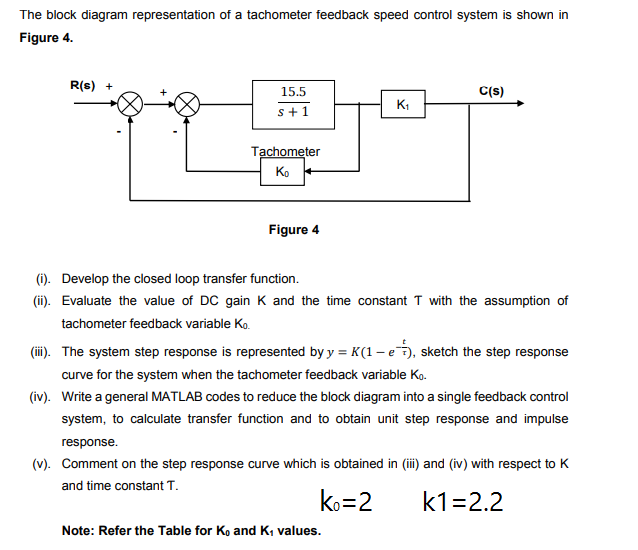

Transcribed Image Text:The block diagram representation of a tachometer feedback speed control system is shown in
Figure 4.
R(s) +
15.5
C(s)
s+1
Tachometer
Ko
Figure 4
(i). Develop the closed loop transfer function.
(ii). Evaluate the value of DC gain K and the time constant T with the assumption of
tachometer feedback variable Ko.
(ii). The system step response is represented by y = K(1 – e), sketch the step response
curve for the system when the tachometer feedback variable Ko.
(iv). Write a general MATLAB codes to reduce the block diagram into a single feedback control
system, to calculate transfer function and to obtain unit step response and impulse
response.
(v). Comment on the step response curve which is obtained in (i) and (iv) with respect to K
and time constant T.
ko=2
k1=2.2
Note: Refer the Table for Ko and K, values.
Expert Solution
This question has been solved!
Explore an expertly crafted, step-by-step solution for a thorough understanding of key concepts.

This is a popular solution

Trending nowThis is a popular solution!

Step by stepSolved in 3 steps with 3 images

Knowledge Booster


Learn more about
Need a deep-dive on the concept behind this application? Look no further. Learn more about this topic, electrical-engineering and related others by exploring similar questions and additional content below.Similar questions
- 5.Consider the feedback system shown in figure. Determine system parameters (a, K, z, p, Ko) to guarantee closed-loop system stability. K. (s+z) K (s +p) e RO E O Y (s² – a²)arrow_forwardQuestion 6 Calculate the gain margin in linear scale of a feedback control loop, when its open loop transfer function has no unstable poles and has associated the Nyquist plot si below, where a=0.71. Give your answer to 2 decimal places. Nyquist Diagram 0.6 0.4 0.2 -0.2 -0.4 -0.6 -2a/5 Real Axis -a/5 -a -4a/5 -3a/5 a/5 Calculate your answer to 2 decimal places.arrow_forward
Recommended textbooks for you
- Introductory Circuit Analysis (13th Edition)Electrical EngineeringISBN:9780133923605Author:Robert L. BoylestadPublisher:PEARSON
 Delmar's Standard Textbook Of ElectricityElectrical EngineeringISBN:9781337900348Author:Stephen L. HermanPublisher:Cengage Learning
 Programmable Logic ControllersElectrical EngineeringISBN:9780073373843Author:Frank D. PetruzellaPublisher:McGraw-Hill Education
  Fundamentals of Electric CircuitsElectrical EngineeringISBN:9780078028229Author:Charles K Alexander, Matthew SadikuPublisher:McGraw-Hill Education
 Electric Circuits. (11th Edition)Electrical EngineeringISBN:9780134746968Author:James W. Nilsson, Susan RiedelPublisher:PEARSON
 Engineering ElectromagneticsElectrical EngineeringISBN:9780078028151Author:Hayt, William H. (william Hart), Jr, BUCK, John A.Publisher:Mcgraw-hill Education,
Introductory Circuit Analysis (13th Edition)
Electrical Engineering
ISBN:9780133923605
Author:Robert L. Boylestad
Publisher:PEARSON
Delmar's Standard Textbook Of Electricity
Electrical Engineering
ISBN:9781337900348
Author:Stephen L. Herman
Publisher:Cengage Learning
Programmable Logic Controllers
Electrical Engineering
ISBN:9780073373843
Author:Frank D. Petruzella
Publisher:McGraw-Hill Education
Fundamentals of Electric Circuits
Electrical Engineering
ISBN:9780078028229
Author:Charles K Alexander, Matthew Sadiku
Publisher:McGraw-Hill Education
Electric Circuits. (11th Edition)
Electrical Engineering
ISBN:9780134746968
Author:James W. Nilsson, Susan Riedel
Publisher:PEARSON
Engineering Electromagnetics
Electrical Engineering
ISBN:9780078028151
Author:Hayt, William H. (william Hart), Jr, BUCK, John A.
Publisher:Mcgraw-hill Education,