Elements Of Electromagnetics
7th Edition
ISBN: 9780190698614
Author: Sadiku, Matthew N. O.
Publisher: Oxford University Press
expand_more
expand_more
format_list_bulleted
Concept explainers
Question
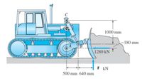
The blade of the bulldozer shown below is rigidly attached to a linkage consisting of the arm AB, which is controlled by the hydraulic cylinder BC. There is an identical linkage on the other side of the bulldozer. Applied loads shown are for both linkages and F = 581 kN.Determine the magnitude of the pin reaction at B in kN.

Transcribed Image Text:1000 mm
-180 mm
B
1280 kN ↑
F kN
500 mm 640 mm
Expert Solution
This question has been solved!
Explore an expertly crafted, step-by-step solution for a thorough understanding of key concepts.
This is a popular solution
Trending nowThis is a popular solution!
Step by stepSolved in 3 steps with 4 images

Knowledge Booster
Learn more about
Need a deep-dive on the concept behind this application? Look no further. Learn more about this topic, mechanical-engineering and related others by exploring similar questions and additional content below.Similar questions
- 3. Draw complete, clearly labeled free-body diagrams. All unknown support reactions should be clearly labeled with a variable name. All known values such as weight or applied forces should be clearly labeled with their known values. Don't need to show equilibrium equations, I just need free-body diagrams. Only solve this text question, not the questions in image.arrow_forwardThe structure shown below is a simplified tower crane. It carries a shipping crate suspended from B that has a weight of 116 kN . The main jib DCB (in green) has a weight of 17 kN concentrated in the center of the beam. This is pinned to the main body at D and is supported by a cable that is routed through pulleys at F and G and is attached to a concrete counterweight J. The main body AEFG (in yellow) is fixed to the ground at A. Various geometry: h1= 26.5 m h2= 3.9 m h3= 5.1 m l1= 12.8 m l2= 17 m l3= 4.3 mm θ= 57.6 degrees Assumptions : The main body AEFG can be considered massless. The cable CFGJ is massless. The pulleys at F and G can be considered massless, frictionless, and of negligible diameter. All bodies are considered rigid. Questions: Determine the weight of counterweight J in order for the main jib DCB to be horizontal. Determine the magnitude of the x and y components of force at pin D. Determine the reactions at fixed support A.arrow_forwardTwo bars connected by a sliding block are shown in the figure. If the effect of friction is not taken into account, perform the following operations: 1.1 Draw the Free Body Diagram (F.B.D.). (1.0 point) 1.2 Determine the moment Ma necessary to keep the system in equilibrium. (1.0 point) 1.3 Determine the magnitude of the reaction at support A. (1.0 point) 1.4 Determine the magnitude of the reaction at support B. (1.0 point) 1.5 Determine the magnitude of the reaction at joint C. (1.0 point)arrow_forward
- Find the horizontal and vertical reactions at the pin at B. Note that the support at D is fixed. Sign convention for the positive x and y direction applies for the answers. Diagram not to scale Answers: (a) -4 kN, 2 kN (b) 4 kN, -2 kN (c) 1.5 kN, 3 kN (d) -1.5 kN, -3 kN 3 kN B A D TTT 2 m 4 kN 2 m C 1m 2 m 5 marrow_forward3 m -3 m *-3 m 3 m B C 4 m H 10 kN 15 kN 5 kN A) Use method of sections to find the forces in CD, DG, and FG. The reaction at E is 13.75 kN. Show your section free body diagram. Use the appropriate descriptions of truss member forces.arrow_forwardPlease solve for all and include all steps. Thxarrow_forward
- The A-frame shown is pin-connected at A, B, C, and D. The surface at E is level and frictionless. Calculate the reaction at E and the reaction components at the pins. - Draw free-body diagram - Solve most simple way, save yourself time - Write out all stepsarrow_forwardNeeds Complete typed solution with 100 % accuracy.arrow_forward
arrow_back_ios
arrow_forward_ios
Recommended textbooks for you
 Elements Of ElectromagneticsMechanical EngineeringISBN:9780190698614Author:Sadiku, Matthew N. O.Publisher:Oxford University Press
 Mechanics of Materials (10th Edition)Mechanical EngineeringISBN:9780134319650Author:Russell C. HibbelerPublisher:PEARSON
 Thermodynamics: An Engineering ApproachMechanical EngineeringISBN:9781259822674Author:Yunus A. Cengel Dr., Michael A. BolesPublisher:McGraw-Hill Education
 Control Systems EngineeringMechanical EngineeringISBN:9781118170519Author:Norman S. NisePublisher:WILEY
 Mechanics of Materials (MindTap Course List)Mechanical EngineeringISBN:9781337093347Author:Barry J. Goodno, James M. GerePublisher:Cengage Learning
 Engineering Mechanics: StaticsMechanical EngineeringISBN:9781118807330Author:James L. Meriam, L. G. Kraige, J. N. BoltonPublisher:WILEY

Elements Of Electromagnetics
Mechanical Engineering
ISBN:9780190698614
Author:Sadiku, Matthew N. O.
Publisher:Oxford University Press

Mechanics of Materials (10th Edition)
Mechanical Engineering
ISBN:9780134319650
Author:Russell C. Hibbeler
Publisher:PEARSON

Thermodynamics: An Engineering Approach
Mechanical Engineering
ISBN:9781259822674
Author:Yunus A. Cengel Dr., Michael A. Boles
Publisher:McGraw-Hill Education

Control Systems Engineering
Mechanical Engineering
ISBN:9781118170519
Author:Norman S. Nise
Publisher:WILEY

Mechanics of Materials (MindTap Course List)
Mechanical Engineering
ISBN:9781337093347
Author:Barry J. Goodno, James M. Gere
Publisher:Cengage Learning

Engineering Mechanics: Statics
Mechanical Engineering
ISBN:9781118807330
Author:James L. Meriam, L. G. Kraige, J. N. Bolton
Publisher:WILEY