
Steel Design (Activate Learning with these NEW titles from Engineering!)
6th Edition
ISBN: 9781337094740
Author: Segui, William T.
Publisher: Cengage Learning
expand_more
expand_more
format_list_bulleted
Related questions
Concept explainers
Question
Give me right solution according to the question
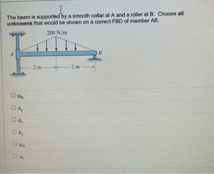

Transcribed Image Text:The beam is supported by a smooth collar at A and a roller at B. Choose all
unknowns that would be shown on a correct FBD of member AB.
200 N/m
2 m
2 m
O Me
DA
B
OB,
O MA
OA
Expert Solution
This question has been solved!
Explore an expertly crafted, step-by-step solution for a thorough understanding of key concepts.

This is a popular solution

Trending nowThis is a popular solution!

Step by stepSolved in 2 steps with 1 images

Knowledge Booster


Learn more about
Need a deep-dive on the concept behind this application? Look no further. Learn more about this topic, civil-engineering and related others by exploring similar questions and additional content below.Similar questions
- Compute the nominal shear strength of an M107.5 of A572 Grad 65 steel.arrow_forwardThe given beam is laterally supported at the ends and at the 1 3 points (points 1, 2, 3, and 4). The concentrated load is a service live load. Use Fy=50 ksi and select a W-shape. Do not check deflections. a. Use LRFD. b. Use ASD.arrow_forwardVerify the value of Zx for a W1850 that is tabulated in the dimensions and properties tables in Part 1 of the Manual.arrow_forward
- If the beam in Problem 5.5-9 i5 braced at A, B, and C, compute for the unbr Cb aced length AC (same as Cb for unbraced length CB). Do not include the beam weight in the loading. a. Use the unfactored service loads. b. Use factored loads.arrow_forwardA plate girder must be designed for the conditions shown in Figure P10.7-4. The given loads are factored, and the uniformly distributed load includes a conservative estimate of the girder weight. Lateral support is provided at the ands and at the load points. Use LRFD for that following: a. Select the, flange and web dimensions so that intermediate stiffeners will he required. Use Fy=50 ksi and a total depth of 50 inches. Bearing stiffeners will be used at the ends and at the load points, but do not proportion them. b. Determine the locations of the intermediate stiffeners, but do not proportion them.arrow_forwardThe member shown in Figure P6.6-4 is part of a braced frame. The load and moments are computed from service loads, and bending is about the x axis (the end shears are not shown). The frame analysis was performed consistent with the effective length method, so the flexural rigidity. EI, was unreduced. Use Kx=0.9. The load and moments are 30 dead load and 70 live load. Determine whether this member satisfies the appropriate AISC interaction equation. a. Use LRFD. b. Use ASD.arrow_forward
arrow_back_ios
arrow_forward_ios
Recommended textbooks for you
- Steel Design (Activate Learning with these NEW ti...Civil EngineeringISBN:9781337094740Author:Segui, William T.Publisher:Cengage Learning
Steel Design (Activate Learning with these NEW ti...
Civil Engineering
ISBN:9781337094740
Author:Segui, William T.
Publisher:Cengage Learning