
Elements Of Electromagnetics
7th Edition
ISBN: 9780190698614
Author: Sadiku, Matthew N. O.
Publisher: Oxford University Press
expand_more
expand_more
format_list_bulleted
Related questions
Concept explainers
Question
thumb_up100%
Determine the state of stress at point B on the cross section of the post at section a-a given that P = 5.5 kN, F = 3.4 kN.
A)Determine the normal stress at point B.
B) Determine the shear stress component [(τxz)V]B at point B.
C) Determine the shear stress component [(τxy)V]B at point B.
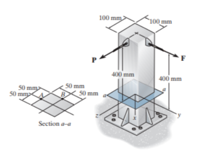

Transcribed Image Text:The image shows a structural diagram of a vertical beam anchored at its base. The main features are labeled with dimensions and forces.
### Diagram Description:
1. **Vertical Beam:**
- The beam has a square cross-section of 100 mm by 100 mm and rises vertically. It is anchored at the base depicted in a shaded area with bolts.
2. **Dimensions:**
- The height from the base to the point where force is applied is 400 mm.
- The distance between certain points on the cross-section is shown as 50 mm.
3. **Forces:**
- Two forces are acting diagonally on opposite sides of the beam:
- Force **F** is applied to the right of the beam.
- Force **P** is applied to the left of the beam.
4. **Cross-Section a-a:**
- A section labeled **a-a** is shown separately, illustrating the detailed arrangement of the cross-section with grid lines at 50 mm intervals. Points **A** and **B** mark specific grid intersections.
5. **Axes:**
- The base is labeled with axes: z-axis coming out towards the viewer, x, and y lie on the plane.
This diagram is typically used to explain concepts of structural mechanics, such as the distribution of forces, bending moments, and stress analysis in beams.
Expert Solution
This question has been solved!
Explore an expertly crafted, step-by-step solution for a thorough understanding of key concepts.

Step by stepSolved in 3 steps with 9 images

Knowledge Booster


Learn more about
Need a deep-dive on the concept behind this application? Look no further. Learn more about this topic, mechanical-engineering and related others by exploring similar questions and additional content below.Similar questions
- The reference state of stress shown in the element sketch below results in the Mohr’s circle plot indicated. For this element, as described below, determine:a)The principal stresses.b)The principal directions (angles to the principal planes).c)The maximum in-plane shear stress.d)Is the maximum in-plane shear stress the absolute maximum shear stress?arrow_forwardThe state of stress at a point in an engine piston is given in the x-y-z coordinates by: 90 180 XX ху [o]= 180 240 0 MPa yx yy yz 120 zy Calculate the deviatoric invariants for the original state of stress, Calculate the principal stresses and the absolute maximum shear stress at the point. What are the stress invariants and the characteristic equation for the transformed state of stress, C. d. earrow_forwardQUESTION 1 PART A AND Barrow_forward
- For the state of plane stress, stress components are shown on the element in Figure Question 1: a) Draw Mohr's circle b) Determine the principal planes and the principal stresses c) The stress components exerted on the element obtained by rotating the given element counterclockwise through 30°. y| 60 MPa x 100 MPa 48 MPaarrow_forwardThe state of stress shown to the left was produced by a combination of loadings on a body that is not shown. Determine the following via Mohr's circle: A) Draw Mohr's Circle for the x-y plane. B) Determine the principal stresses - All 3. C) Sketch a properly oriented differential element showing the principal stresses in the x-y plane. D) Determine the magnitude of the maximum shear stress in the x-y plane. E) Sketch a properly oriented differential element showing the maximum shear stress state in the x-y plane. F) Determine the magnitude of the absolute maximum shear stress (and include the two out of plane circles on your original figure). Use the following values for the magnitudes of the stresses: x = 0₂ Txy Ox X X 10 ksi, σy = 4 ksi, σ₂ = 3 ksi, Txy = 4 ksiarrow_forwardThe state of stress at a point in a member is shown on the element. Suppose that σx= 25 MPa, σy= 100 MPa, and τxy= 53 MPa. A) Determine the normal stress acting on the plane AB. B) Determine the shear stress acting on the plane AB.arrow_forward
- Please solve in a handwritten format. Don't use chatgpt. Mechanical engineeringarrow_forwardThe state of stress at a point under plane stress condition is Ox = 100 MPa, Oy = 50 MPa, Txy = 20 MPa %3D The radius of the Mohr's circle representing the given state of stress in MPa is: O 32.02 O5071 O60 23 O 100.92arrow_forwardq1 b In 2D XY-plane-stress analysis, how many stress components you need to calculate.Please write/show their names in XY plane on a plane element.arrow_forward
arrow_back_ios
arrow_forward_ios
Recommended textbooks for you
- Elements Of ElectromagneticsMechanical EngineeringISBN:9780190698614Author:Sadiku, Matthew N. O.Publisher:Oxford University Press
 Mechanics of Materials (10th Edition)Mechanical EngineeringISBN:9780134319650Author:Russell C. HibbelerPublisher:PEARSON
 Thermodynamics: An Engineering ApproachMechanical EngineeringISBN:9781259822674Author:Yunus A. Cengel Dr., Michael A. BolesPublisher:McGraw-Hill Education
  Control Systems EngineeringMechanical EngineeringISBN:9781118170519Author:Norman S. NisePublisher:WILEY
 Mechanics of Materials (MindTap Course List)Mechanical EngineeringISBN:9781337093347Author:Barry J. Goodno, James M. GerePublisher:Cengage Learning
 Engineering Mechanics: StaticsMechanical EngineeringISBN:9781118807330Author:James L. Meriam, L. G. Kraige, J. N. BoltonPublisher:WILEY
Elements Of Electromagnetics
Mechanical Engineering
ISBN:9780190698614
Author:Sadiku, Matthew N. O.
Publisher:Oxford University Press
Mechanics of Materials (10th Edition)
Mechanical Engineering
ISBN:9780134319650
Author:Russell C. Hibbeler
Publisher:PEARSON
Thermodynamics: An Engineering Approach
Mechanical Engineering
ISBN:9781259822674
Author:Yunus A. Cengel Dr., Michael A. Boles
Publisher:McGraw-Hill Education
Control Systems Engineering
Mechanical Engineering
ISBN:9781118170519
Author:Norman S. Nise
Publisher:WILEY
Mechanics of Materials (MindTap Course List)
Mechanical Engineering
ISBN:9781337093347
Author:Barry J. Goodno, James M. Gere
Publisher:Cengage Learning
Engineering Mechanics: Statics
Mechanical Engineering
ISBN:9781118807330
Author:James L. Meriam, L. G. Kraige, J. N. Bolton
Publisher:WILEY