
Mechanics of Materials (MindTap Course List)
9th Edition
ISBN: 9781337093347
Author: Barry J. Goodno, James M. Gere
Publisher: Cengage Learning
expand_more
expand_more
format_list_bulleted
Related questions
Concept explainers
Question
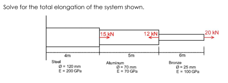

Transcribed Image Text:Solve for the total elongation of the system shown.
15 kN
12 kN
20 kN
4m
5m
6m
Steel
Ø = 120 mm
E = 200 GPa
Aluminum
Ø = 70 mm
E = 70 GPa
Bronze
Ø = 25 mm
E = 100 GPa
Expert Solution
This question has been solved!
Explore an expertly crafted, step-by-step solution for a thorough understanding of key concepts.

This is a popular solution

Trending nowThis is a popular solution!

Step by stepSolved in 2 steps with 2 images

Knowledge Booster


Learn more about
Need a deep-dive on the concept behind this application? Look no further. Learn more about this topic, mechanical-engineering and related others by exploring similar questions and additional content below.Similar questions
- F2 Q1) Axial displacement of point C in the system shown on the left is 0.01 cm. Find the maximum elongation of the bar and the maximum normal stress. A F1 A. GIVEN: F2 = 100 kN, (1 = 240 cm, €2= 160 cm, bi = 5 cm, bz=10 cm, h=5 cm, E=2.107 N/em², a=20 cm Note: neglect stress concentration. h bị b2 A-A sectionarrow_forward5. If the elongation of wire BC is 0.2 mm after the force P is applied, determine the magnitude of P. The wire is A-36 steel and has a diameter of 3 mm. (Esteel = 200 GPa) 300 mm -200 mm- B 400 mm - [Ans: P = 628 N]arrow_forwardHello sir, please, the solution and the solution line is as in books, I mean, not manual, please, sir, please, the line is as in books.arrow_forward
- Determine the horizontal displacement of end point D of the steel rod shown in the figure. E = 200 GPa A = 200 mm² A = 600 mm² A B ka 300 kN 0.3 m Your answer: 0.3 m 0.25 mm to the left 0.25 mm to the right 1.25 mm to the right 1.25 mm to the left 1.75 mm to the right C 200 KN 0.4 m- D 100 kNarrow_forwardWhy isn’t the force in “CE”= 10root5, because 10^2+20^2=10root5 and not 10root2.arrow_forward2-16. The tapered steel bar shown in the figure is cut out from a steel plate 25 mm thick and is welded at the top to a rigid structure. Find the deflection of the end A caused by the force of 40 kN applied at B. Consider the origin of the coordinate axes at the point of intersection of the sloping lines. E = 210 GN/m². Ans: 0.093 mm. 150 mm 1.5 m 40 kN B 1.5 m 50 mm PROB. 2 – 16arrow_forward
- Give proper explanation and don't copy from google or any other websitearrow_forwardShow the zero force members on the figure (label them on the figure and list them on the side). (Note: you don't have to solve the entire structure) D E 60 kips В F A M L K J G Н 180 kips 120 kipsarrow_forwardThe assembly consists of three titanium (Ti-6A1- 4V) rods and a rigid bar AC. The cross-section area of each rod is given in the figure. If a force of 60 kip is applied o the ring F, determine the horizontal displacement of point F. Hint: Refer to the textbook appendix for material properties. AEF 2 in² 1 ft = 60 kip F-2 ft- 2 ft A C 6 ft B AAB = 1 in² E ACD = 1.5 in² 6 ft Darrow_forward
- 3) For the given plate subjected to two point forces, calculate the nodal displacements and the moments at points A and B. (Note that A is the mid-point of the finite element) E = 30000 MPa h = 0.14 m v = 0.20 2 m 2 m 50 kN 2 m 50 kN A B 50 kN 50 kN 2 m 50 Cross-section along the symmetry axisarrow_forwardCan someone help me to my activity to understand this. Thank you!! :))arrow_forwardThe assembly consists of three steel rods (E=13 x 106 psi) and a rigid bar AC. The cross-sectional area of each rod is given in Figure 1. If a force of 6.5 kip is applied to the ring F, determine the horizontal displacement of point F. D 4 ft AcD = 1.5 in? 2 ft F E 1 ft 6.5 kip 1 ft AEF = 2.1 in? A AB = 1.3 in? 6 ft Figure 1arrow_forward
arrow_back_ios
SEE MORE QUESTIONS
arrow_forward_ios
Recommended textbooks for you
- Mechanics of Materials (MindTap Course List)Mechanical EngineeringISBN:9781337093347Author:Barry J. Goodno, James M. GerePublisher:Cengage Learning
Mechanics of Materials (MindTap Course List)
Mechanical Engineering
ISBN:9781337093347
Author:Barry J. Goodno, James M. Gere
Publisher:Cengage Learning