
Elements Of Electromagnetics
7th Edition
ISBN: 9780190698614
Author: Sadiku, Matthew N. O.
Publisher: Oxford University Press
expand_more
expand_more
format_list_bulleted
Related questions
Question
What is the kinematic equations relating the end-effecter position and orientation
to the joint displacements.
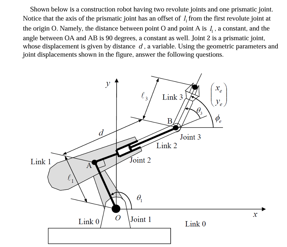

Transcribed Image Text:Shown below is a construction robot having two revolute joints and one prismatic joint.
Notice that the axis of the prismatic joint has an offset of 1 from the first revolute joint at
the origin O. Namely, the distance between point O and point A is 1, a constant, and the
angle between OA and AB is 90 degrees, a constant as well. Joint 2 is a prismatic joint,
whose displacement is given by distance d, a variable. Using the geometric parameters and
joint displacements shown in the figure, answer the following questions.
y
Link 3
B
Joint 3
Link 2
Link 1
Joint 2
A
Ꮎ
Link 0
Joint 1
Link 0
x
e
x
Expert Solution
This question has been solved!
Explore an expertly crafted, step-by-step solution for a thorough understanding of key concepts.

Step by stepSolved in 2 steps with 6 images

Knowledge Booster

Similar questions
- Derive the equation of motion for the following system, using (the rotation of the beam about the hinge) as the degree-of-freedom. Not that there is an applied force (F, sin wt) as well as an applied moment (Mo sin wt). The total bar mass is m. Treat the bar as two bars: one to the left of the hinge point; one to the right. The one to the left has a mass moment of inertia of 2 mL²; the one to the 27 192 Fo sin cor right has a mass moment of inertia of mL². Then transform this differential equation of the Laplace domain, assuming zero initial 192 conditions. Lastly, compute the damping ratio and damped natural frequency for this system. 1/4+1/12 mo LUC m Mo sin corarrow_forward8. A Hooke's joint connects two shafts whose axes intersect at 150°. The driving shaft rotates uni- formly at 120 r.p.m. The driven shaft operates against a steady torque of 150 N-m and carries a flywheel whose mass is 45 kg and radius of gyration 150 mm. Find the maximum torque which will be exerted by the driving shaft. [Ans. 187 N-m] mumarrow_forwardDerive the equation of motion for the following system, using (the rotation of the beam about the hinge) as the degree-of-freedom. Not that there is an applied force (Fo sin wt) as well as an applied moment (Mo sin wt). The total bar mass is m. Treat the bar as two bars: one to the left of the hinge point; one to the right. The one to the left has a mass moment of inertia of- mL²; the one to the 27 192 1 mL². Then transform this Fo sin cor right has a mass moment of inertia of- 192 differential equation of the Laplace domain, assuming zero initial conditions. Lastly, compute the damping ratio and damped natural frequency for this system. TET 4 fm o Mo sin orarrow_forward
- Block String Rod Disk Mech 3. As shown above, a uniform disk is mounted to an axle and is free to rotate without friction. A thin uniform rod is rigidly attached to the disk so that it will rotate with the disk. A block is attached to the end of the rod. Properties of the disk, rod, and block are as follows. Disk: Зт, radius R, moment of inertia about center ID = mR² mass = %3D Rod: m, length = 2R, moment of inertia about one end IR mR? mass = Block: mass = 2m The system is held in equilibrium with the rod at an angle 0, to the vertical, as shown above, by a horizontal string of negligible mass with one end attached to the disk and the other to a wall. Express your answers to the following in terms of m, R, 00, and g. (a) Determine the tension in the string.arrow_forwardplease i need her solving with using the formulas attached below of pin joint linkagearrow_forwardTask 3 Generate free body diagram for the following mechanism: C B 4 m E D m 6 m -8 m-arrow_forward
- PROBLEM 2: The crank shown is free to rotate at B about the x-axis only. Given the following dimensions: x1 = 53 cm x2 = 25 cm Y₁ = 74 cm 2₁ = 29 cm A 100-N force is applied at A with the following spatial angles: From positive x-axis: a = 64° From positive y-axis: B = 119° It is known that the angle from positive z-axis is obtuse, 90° ≤ y ≤ 180⁰ Required: 1. Determine the moment about B due to the applied force at A. INCLUDE (-) NEGATIVE SIGN IF NECESSARY, FOR THIS ITEM ONLY. MA = k N-m use 2 decimal places 2. Determine the component of the force along line AB. 1+ 8= j+ PAB = Nuse 2 decimal places 3. Find the angle between the force applied and its component along line AB. use 3 decimal placesarrow_forwardQ3/ For the crank- connecting rod mechanism shown: OA= 10cm , AB= 30 cm, AC= 10 cm, it's single degree of freedom coordinate is e. If angular velocity of OA=30 rad/sec. Find angular velocity AB at e = (30)° crank angle. A C 8.7 rad/sec O23 rad/sec O 16.3 rad/secarrow_forwardFigure 1.1 shows a crank, OA = 72 mm long which rotates anticlockwise about O at w = .A straight bar DBC is pivoted at B, which is 150 mm vertically below O and the rev 150 min length BC = 75 mm. The portion BD of this bar slides in a trunnion fitted at A on the crank OA. A slider E slides in horizontal guides 30 mm below B, and is connected to C by a rod CE = 240 mm long. For the position shown, where angle AOB = 120°, 1.1. Construct a space diagram 1.2. Construct a velocity diagram then 1.3. Find the linear velocity of slider E 120 E Figure 1.1 Plain mechanismarrow_forward
- 2. (A) Sketch the kinematic diagram of the following mechanism shown and give brief description on how each link move relative to each other. (B) compute the degree of freedom. (C) Determine the location of all revolute pairs shown in the figure as revolute pairs J and K moves to J' and K'. Use the actual size based on the figure below. z, OVERHEAD LOADERarrow_forwardRequired information The figure shows a weapon called a battering ram (modern large battering rams are typically mounted on armored vehicles). The ram has a weight W,= 2500 lb, center of mass at E, and radius of gyration kf= 6.5 ft. The distance between points A and B and between points Cand D is 6 ft. Consider h= 4.5 ft and d= 3 ft. The connections at points A, B, C, and D are pin connections, and assume that the cart does not move while the ram swings. Assume that AB and CD are inextensible cords with negligible mass. In addition, assume that, at the instant shown, e = 10° and the ram is swinging forward with v E = 4.5 ft/s. -d-l ram E At this instant, determine the acceleration of E, as well as the tensions in the cords AB and CD. The acceleration of E is a E ]î) fu/s?. = The tension in the cord AB is Ib The tension in the cord CD is Ib 7.arrow_forwardSolve it correctly please. I will rate accordingly with 4votes.arrow_forward
arrow_back_ios
SEE MORE QUESTIONS
arrow_forward_ios
Recommended textbooks for you
- Elements Of ElectromagneticsMechanical EngineeringISBN:9780190698614Author:Sadiku, Matthew N. O.Publisher:Oxford University Press
 Mechanics of Materials (10th Edition)Mechanical EngineeringISBN:9780134319650Author:Russell C. HibbelerPublisher:PEARSON
 Thermodynamics: An Engineering ApproachMechanical EngineeringISBN:9781259822674Author:Yunus A. Cengel Dr., Michael A. BolesPublisher:McGraw-Hill Education
  Control Systems EngineeringMechanical EngineeringISBN:9781118170519Author:Norman S. NisePublisher:WILEY
 Mechanics of Materials (MindTap Course List)Mechanical EngineeringISBN:9781337093347Author:Barry J. Goodno, James M. GerePublisher:Cengage Learning
 Engineering Mechanics: StaticsMechanical EngineeringISBN:9781118807330Author:James L. Meriam, L. G. Kraige, J. N. BoltonPublisher:WILEY
Elements Of Electromagnetics
Mechanical Engineering
ISBN:9780190698614
Author:Sadiku, Matthew N. O.
Publisher:Oxford University Press
Mechanics of Materials (10th Edition)
Mechanical Engineering
ISBN:9780134319650
Author:Russell C. Hibbeler
Publisher:PEARSON
Thermodynamics: An Engineering Approach
Mechanical Engineering
ISBN:9781259822674
Author:Yunus A. Cengel Dr., Michael A. Boles
Publisher:McGraw-Hill Education
Control Systems Engineering
Mechanical Engineering
ISBN:9781118170519
Author:Norman S. Nise
Publisher:WILEY
Mechanics of Materials (MindTap Course List)
Mechanical Engineering
ISBN:9781337093347
Author:Barry J. Goodno, James M. Gere
Publisher:Cengage Learning
Engineering Mechanics: Statics
Mechanical Engineering
ISBN:9781118807330
Author:James L. Meriam, L. G. Kraige, J. N. Bolton
Publisher:WILEY