Delmar's Standard Textbook Of Electricity
7th Edition
ISBN: 9781337900348
Author: Stephen L. Herman
Publisher: Cengage Learning
expand_more
expand_more
format_list_bulleted
Question

Transcribed Image Text:!
Required information
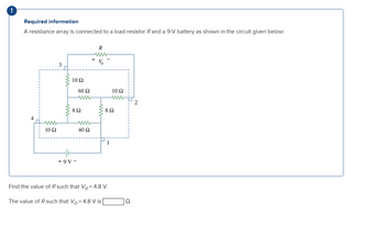
A resistance array is connected to a load resistor R and a 9-V battery as shown in the circuit given below:
3
R
www
V
10 Ω
60 Ω
10 Ω
ww
2
802
802
10 Ω
40 Ω
1
+9V-
Find the value of R such that Vo= 4.8 V.
The value of R such that Vo = 4.8 V is
Ω.
Expert Solution
This question has been solved!
Explore an expertly crafted, step-by-step solution for a thorough understanding of key concepts.
Step by stepSolved in 2 steps with 2 images

Knowledge Booster
Similar questions
- 2. Determine the voltage with respect to ground at each point in below. Assume the practical model. Solve and Simulate to compare the result. D1 D2 C R A B D 1.0 kΩ + Vs2 8 V VsI 25 Varrow_forwardEach of the cells shown in the figure has an emf of 1.50 V and a 0.0750-ohm internalresistance. Find I1, I2, and I3.arrow_forwardDetermine the voltage V1 in Volts for the following circuit with component values ISRC = 1.5 mA, VSRC = 7 V, R1 = 2.2 kQ, R2 = 3.4 k2, and R3 = 1.0 kQ. 11 Vsrc Isrc + V1 + R1 m R2 R3 m 12 13arrow_forward
- Resistors Circuits I Each of the circuits below consists of a battery and several resistors. Several of the voltages, currents, and resistances are indicated. Use both of Kirchoff's Laws and Ohm's Law to determine as many of the other voltages, currents, and resistances as possible.arrow_forward1. A voltage divider circuit is shown below. V in R₁ www R₂ www Vout V out Circuit theory tells us that the voltage, V2, across resistor R₂ should be given by: R₂ R₁ + R₂ If Vin is 10 volts, R₁ is 120 ohm and R₂ is 500 ohm, what is the expected output voltage? Vinarrow_forward6arrow_forward
- Determine the voltage V1 in Volts for the following circuit with component values ISRC = 1.6 mA, VSRC = 6 V, R1 = 2.3 k2, R2 = 3.5 kQ, and R3 = 1.3 kQ. Vsrc + R1 w R2 w Isrc V1 + R3 www 11 12 4 13arrow_forwardFor the circuit below, determine the voltage across resistors R1: The two sources V1 and V2 are cosine voltage sources: V1: Vp = 20 V, 0 = 0°, o = 1250 rad/secs V2: Vp = 12 V, 0 = 45°, o = 1250 rad/secs L1 C1 HH 15u 20mH R2 35 V1 V2 VOFF = 0 VAMPL = 12 FREQ = 198.94 AC = 0 VOFF = 0 VAMPL = 20 FREQ = 198.94 AC = 0 R1 10arrow_forwardDetermine the value of the resistance R in the circuit shown. 5 ΚΩ 10 ko 25 V 4 ip R 0.5 mA 2:43 PM O 59°F Partly sunny 2/27/2022 P Type here to search Del End F10 PgDn F12 PrtScn Home Ins Esc F5 F6 F7 F3 @ 2$ & Backspa %D 8 2 3 4.arrow_forward
- Q2 Please respond to question in attached image. Thank you.arrow_forwardResistors Circuits I Each of the circuits below consists of a battery and several resistors. Several of the voltages, currents, and resistances are indicated. Use both of Kirchoff's Laws and Ohm's Law to determine as many of the other voltages, currents, and resistances as possible.arrow_forwardSuppose you have the following circuit diagram. Here R1=22kΩ, R2=33kΩ, R3=1.1kΩ, R4=3.3kΩ, R5=33kΩ, R6=11kΩ, R7=33kΩ, R8=1.1kΩ, R9=3.3kΩ are the resistances on the circuit where kΩ stands for kilo ohm. The electromotive forces of the batteries are E1=3volts and E2=6volts. Calculate the current through R_bk and call it I_bk.arrow_forward
arrow_back_ios
SEE MORE QUESTIONS
arrow_forward_ios
Recommended textbooks for you
 Delmar's Standard Textbook Of ElectricityElectrical EngineeringISBN:9781337900348Author:Stephen L. HermanPublisher:Cengage Learning

Delmar's Standard Textbook Of Electricity
Electrical Engineering
ISBN:9781337900348
Author:Stephen L. Herman
Publisher:Cengage Learning