
Elements Of Electromagnetics
7th Edition
ISBN: 9780190698614
Author: Sadiku, Matthew N. O.
Publisher: Oxford University Press
expand_more
expand_more
format_list_bulleted
Related questions
Concept explainers
Question
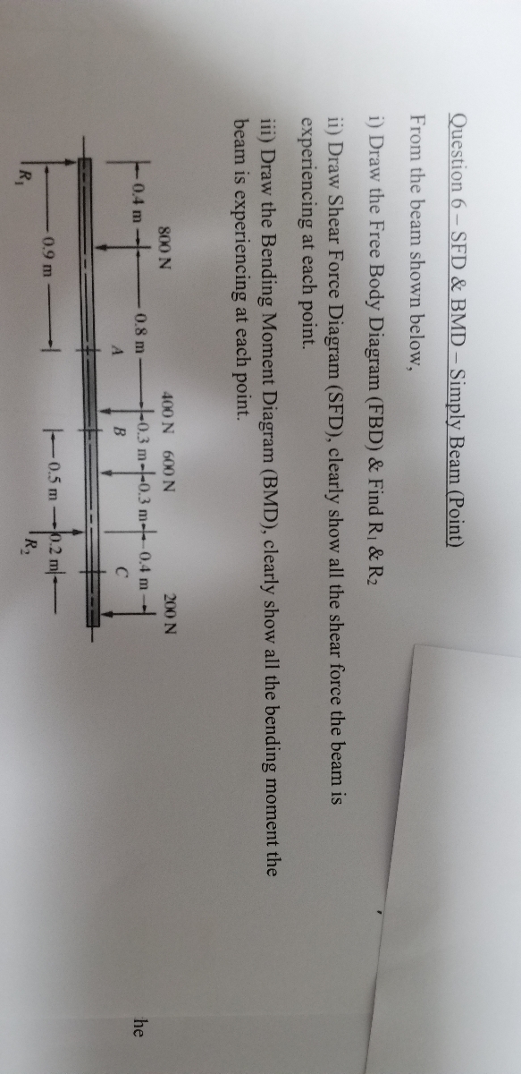

Transcribed Image Text:Question 6- SFD & BMD- Simply Beam (Point)
From the beam shown below,
i) Draw the Free Body Diagram (FBD) & Find R1 & R2
ii) Draw Shear Force Diagram (SFD), clearly show all the shear force the beam is
experiencing at each point.
iii) Draw the Bending Moment Diagram (BMD), clearly show all the bending moment the
beam is experiencing at each point.
800 N
400 N 600 N
200 N
0.4 m-
0.8 m
t0.3 m--0.3 m-0.4 m-
he
C
A.
0.9 m
0.5 m-.2 m-
R2
R1
Expert Solution
This question has been solved!
Explore an expertly crafted, step-by-step solution for a thorough understanding of key concepts.

This is a popular solution

Trending nowThis is a popular solution!

Step by stepSolved in 2 steps with 2 images

Knowledge Booster


Learn more about
Need a deep-dive on the concept behind this application? Look no further. Learn more about this topic, mechanical-engineering and related others by exploring similar questions and additional content below.Similar questions
- 7) Consider the beam in the figure below. Take w = 50 kN/m. The 40 kN force makes an angle of 60 degrees with the horizontal. Assume the thickness of the beam is small. Part A) What are the support reactions at A and B? Nc= Part B) Determine the internal normal force at point C in the beam. Vc= W Part D) beam. -2 m- Part C). Determine the absolute value of the internal shear force at point C in the beam. Mc = 40 kN Determine the absolute value of the internal bending moment at point C in thearrow_forwardPart A was already answered so can you do part Barrow_forwardi need the answer quicklyarrow_forward
- a) the value of the maximum bending moment in the beam. Enter your answer in kNm to three decimal places. b) the maximum normal stress in the cross-section of the beam. Enter the positive value of the stress. Enter your answer in MPa to two decimal places.arrow_forwardI need correct answer and all the parts I'll rate and handwritten only otherwise skip Note- handwritten onlyarrow_forwardBrandon is trying to create a cool shelf bracket using pipes like he saw on Instagram. He is concerned about the pipe unscrewing from the wall bracket at A. He wants to know how likely it is that it will unscrew. Using some combination of drawings and written statements, answer the following questions. 1) What moment direction/axis would be critical to the pipe unscrewing at A? 2) Based on the current geometry, which force direction of F is most likely to create the moment described in part 1? 3) If the weight of the books acts only downwards, how could he modify his bracket so it cannot unscrew? You can use any combination of the parts shown (no need to use all of them). Show where the now vertical load F will be applied. Explain why your new design will be less likely to get unscrewed at A. x B 0.5 m 0.4 m A 0.3 m 0.3 marrow_forward
- Figure shows the loading system on the beam. a) Calculate the reactions at the support RA and RB b) Using suitable scale, draw the shear force and bending moment diagrams of the given beam. c) Determine the value of the maximum bending moment of the beam. 12 kN +0.5m RA 3 kN/m 8 kN/m 4m 11 kN + 1m RBarrow_forwardP= 4 kN w= 0.8 kN/m a) Start with the shear diagram. To use a segment of the left end of the beam to develop the expression for the shear, the vertical reaction at A must be known. Calculate the vertical reaction at A. Let a positive force act up. b)Write an expression for the internal shear for an arbitrary point between A and B c)Write an expression for the internal shear for an arbitrary point between B and C.arrow_forwardProblem 1) Create the appropriate diagrams for the following system. (Load, Shear, and Moment) Identify and comment on the most interesting points. 25 kN/m 5 m 20 kN-m Barrow_forward
- Hello Good Afternoon Sir,I have a question in my homework related structural statics lesson. The following below is my question. Please advice. Thank you so much Regards,Irfanarrow_forwardc) The same rectangular cross-section beam in Q2b is subjected to a maximum bending moment of 25,000 Nm and experiences sagging. Assuming that the centroidal axis passes through the beam section at (d/2), calculate the maximum bending stress (?max) the beam will experience. Give your answer in N/mm2 and to 2 decimal places.arrow_forwardGggarrow_forward
arrow_back_ios
SEE MORE QUESTIONS
arrow_forward_ios
Recommended textbooks for you
- Elements Of ElectromagneticsMechanical EngineeringISBN:9780190698614Author:Sadiku, Matthew N. O.Publisher:Oxford University Press
 Mechanics of Materials (10th Edition)Mechanical EngineeringISBN:9780134319650Author:Russell C. HibbelerPublisher:PEARSON
 Thermodynamics: An Engineering ApproachMechanical EngineeringISBN:9781259822674Author:Yunus A. Cengel Dr., Michael A. BolesPublisher:McGraw-Hill Education
  Control Systems EngineeringMechanical EngineeringISBN:9781118170519Author:Norman S. NisePublisher:WILEY
 Mechanics of Materials (MindTap Course List)Mechanical EngineeringISBN:9781337093347Author:Barry J. Goodno, James M. GerePublisher:Cengage Learning
 Engineering Mechanics: StaticsMechanical EngineeringISBN:9781118807330Author:James L. Meriam, L. G. Kraige, J. N. BoltonPublisher:WILEY
Elements Of Electromagnetics
Mechanical Engineering
ISBN:9780190698614
Author:Sadiku, Matthew N. O.
Publisher:Oxford University Press
Mechanics of Materials (10th Edition)
Mechanical Engineering
ISBN:9780134319650
Author:Russell C. Hibbeler
Publisher:PEARSON
Thermodynamics: An Engineering Approach
Mechanical Engineering
ISBN:9781259822674
Author:Yunus A. Cengel Dr., Michael A. Boles
Publisher:McGraw-Hill Education
Control Systems Engineering
Mechanical Engineering
ISBN:9781118170519
Author:Norman S. Nise
Publisher:WILEY
Mechanics of Materials (MindTap Course List)
Mechanical Engineering
ISBN:9781337093347
Author:Barry J. Goodno, James M. Gere
Publisher:Cengage Learning
Engineering Mechanics: Statics
Mechanical Engineering
ISBN:9781118807330
Author:James L. Meriam, L. G. Kraige, J. N. Bolton
Publisher:WILEY