Concept explainers
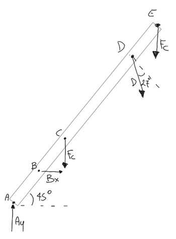
Hi, can you help me understand the direction and magnitude of the perpendicular forces applied to this beam? It's important cause I need to calculate the bending and shear moment, but I'm having trouble understanding the direction of the forces and magnitude of the forces.
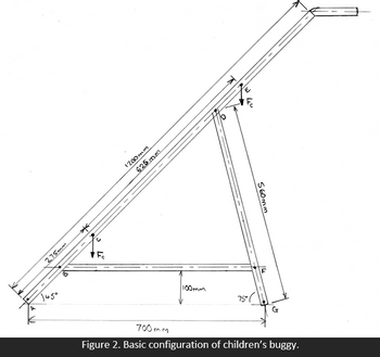
At points C and E there is a force Fc applied of 49 N. At point D there is a force applied of 61.1 N. At point B the force applied is 18.9 N and at point A a force of 39.84 N is applied. These forces have been calculated previously in other calculations.
Figure 2 is the main structure I am analysing for the problem, but I have to calculate the bending and shear force only to the beam where A, B, C, D and E forces are applied. Could you please help me?


Step by stepSolved in 3 steps with 19 images

- Hi can someone explain how I got this wrong and give the right answer pleasearrow_forwardFor the following beams shown, (1) Derive the shear force and bending moment equations; and (2) draw the shear force and bending moment diagrams. Neglect the weight of the beam.arrow_forwardHi can you please fully complete the 3 tasks, struggling with the question and need it to study, thanks very mucharrow_forward
- Hello Good Afternoon Sir,I have a question in my homework related structural statics lesson. The following below is my question. Please advice. Thank you so much Regards,Irfanarrow_forwardSHEAR AND MOMENT DIAGRAM PROBLEM 2 Use the AREA method to construct the shear-force and bending-moment diagrams for the beam shown. Let a = 6.9 ft, b = 10.4 ft, c = 5.8 ft, and w = 9.5 kips/ft. Label all significant points on each diagram and identify the maximum moments (both positive and negative) along with their respective locations. Clearly differentiate straight-line and curved portions of the diagrams. Determine the maximum shear force and bending moment in the beam. Note that answers may be positive or negative. Here, "maximum" refers to the largest magnitude value, but you should enter your shear force and bending moment with the correct sign, using the sign convention. If the magnitudes of the largest positive and largest negative values are the same, enter a positive number. The roller at point D indicates that motion is restricted both up and down, and the beam will not lift off the roller. a B W b C D Xarrow_forwardAnswer it correctly and explain. I will rate and review accordingly.arrow_forward
- 3.15 Plot the shear force and bending moment diagrams of the beam loaded as shown in the figure qa²/2 A a аarrow_forwardPart 1 For the simply supported beam subjected to the loading shown, derive equations for the shear force V and the bending moment M for any location in the beam. (Place the origin at point A.) Let a=11.5 ft, b-5.0 ft, c= 8.0 ft, w = 7 kips/ft and M = 250 kip-ft. Construct the shear-force and bending-moment diagrams on paper and use the results to answer the questions in the subsequent parts of this GO exercise. A Answers: Ay = Calculate the reaction forces Ay and C, acting on the beam. Positive values for the reactions are indicated by the directions of the red arrows shown on the free-body diagram below. (Note: Since Ax = 0, it has been omitted from the free-body diagram.) Cy= Part 2 Answers: (a) V= (c) V= (b) V- i i (e) V- (d) V- i Part 3 (a) M- i Determine the shear force acting at each of the following locations: (a)x=0+ ft (i.e., just to the right of support A) (b) x 11.5 ft (i.e., at point B) (c) x 16.5-ft (i.e., just to the left of the support C) (d) x = 16.5+ ft (i.e., just to…arrow_forwardB4arrow_forward
 Elements Of ElectromagneticsMechanical EngineeringISBN:9780190698614Author:Sadiku, Matthew N. O.Publisher:Oxford University Press
 Mechanics of Materials (10th Edition)Mechanical EngineeringISBN:9780134319650Author:Russell C. HibbelerPublisher:PEARSON
 Thermodynamics: An Engineering ApproachMechanical EngineeringISBN:9781259822674Author:Yunus A. Cengel Dr., Michael A. BolesPublisher:McGraw-Hill Education
 Control Systems EngineeringMechanical EngineeringISBN:9781118170519Author:Norman S. NisePublisher:WILEY
 Mechanics of Materials (MindTap Course List)Mechanical EngineeringISBN:9781337093347Author:Barry J. Goodno, James M. GerePublisher:Cengage Learning
 Engineering Mechanics: StaticsMechanical EngineeringISBN:9781118807330Author:James L. Meriam, L. G. Kraige, J. N. BoltonPublisher:WILEY


