Structural Analysis
6th Edition
ISBN: 9781337630931
Author: KASSIMALI, Aslam.
Publisher: Cengage,
expand_more
expand_more
format_list_bulleted
Concept explainers
Question
thumb_up100%
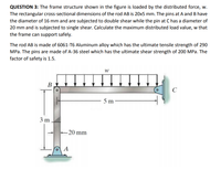
: The frame structure shown in the figure is loaded by the distributed force, w.
The rectangular cross-sectional dimensions of the rod AB is 20x5 mm. The pins at A and B have
the diameter of 16 mm and are subjected to double shear while the pin at C has a diameter of
20 mm and is subjected to single shear. Calculate the maximum distributed load value, w that
the frame can support safely.
The rod AB is made of 6061-T6 Aluminum alloy which has the ultimate tensile strength of 290
MPa. The pins are made of A-36 steel which has the ultimate shear strength of 200 MPa. The
factor of safety is 1.5.

Transcribed Image Text:QUESTION 3: The frame structure shown in the figure is loaded by the distributed force, w.
The rectangular cross-sectional dimensions of the rod AB is 20x5 mm. The pins at A and B have
the diameter of 16 mm and are subjected to double shear while the pin at C has a diameter of
20 mm and is subjected to single shear. Calculate the maximum distributed load value, w that
the frame can support safely.
The rod AB is made of 6061-T6 Aluminum alloy which has the ultimate tensile strength of 290
MPa. The pins are made of A-36 steel which has the ultimate shear strength of 200 MPa. The
factor of safety is 1.5.
В
C
5 m
3 m
-20 mm
A
Expert Solution
This question has been solved!
Explore an expertly crafted, step-by-step solution for a thorough understanding of key concepts.
This is a popular solution
Trending nowThis is a popular solution!
Step by stepSolved in 5 steps with 1 images

Knowledge Booster
Learn more about
Need a deep-dive on the concept behind this application? Look no further. Learn more about this topic, civil-engineering and related others by exploring similar questions and additional content below.Similar questions
- Question # 1: Determine the force in each member of the truss and state if the members are in tension or compression. 300 lb 600 15 B 60015 GOO G 11. 244in. 6 ft load at point B, D, F = 600 lb load at pount A and H=300 lb distance AC = CE =EG = GH = 8FT -80---SA- [Answer: FAB=15001b-C. Fac-12001b-T, Fac0, For-12001b-T, Fan+ 12001b-C, F₁-601b-C. Form 721h-T, Use symmetry to obtain the rest of the members]arrow_forward2arrow_forwardthis is a structural analysis question please answer it ASAP thank you in advancearrow_forward
- Determine the force of the members for the space truss shown in the figure. Joints A and B are supported by ball-and-socket while Joint C is supported by short link along z-axis. Indicate whether member is tension (T) or compression (C). 2m y Sm Az By BX Bz PAR Ax CSXScanned with Ca canner a SISU KN 15m 1 2117arrow_forward: Consider the truss shown in the figure below, and answer the following questions. Figure is not to scale. P P R K 5 m B C D E F - 2 m --2 m - 2 m - 2 m- 2 m-- 2 m - a) If P and R are non-zero forces and Q = 0 kN, indicate all the zero-force members in the truss. O LB O LC O KC O KD O JD O ID O IE О НЕ О НЕ O None b) Following from the situation described in Part (a), how many additional zero-force members will there be in the truss in the following situation? If the force R acting at node H is removed.arrow_forward
arrow_back_ios
arrow_forward_ios
Recommended textbooks for you

 Structural Analysis (10th Edition)Civil EngineeringISBN:9780134610672Author:Russell C. HibbelerPublisher:PEARSON
 Principles of Foundation Engineering (MindTap Cou...Civil EngineeringISBN:9781337705028Author:Braja M. Das, Nagaratnam SivakuganPublisher:Cengage Learning
 Fundamentals of Structural AnalysisCivil EngineeringISBN:9780073398006Author:Kenneth M. Leet Emeritus, Chia-Ming Uang, Joel LanningPublisher:McGraw-Hill Education
 Traffic and Highway EngineeringCivil EngineeringISBN:9781305156241Author:Garber, Nicholas J.Publisher:Cengage Learning


Structural Analysis (10th Edition)
Civil Engineering
ISBN:9780134610672
Author:Russell C. Hibbeler
Publisher:PEARSON

Principles of Foundation Engineering (MindTap Cou...
Civil Engineering
ISBN:9781337705028
Author:Braja M. Das, Nagaratnam Sivakugan
Publisher:Cengage Learning

Fundamentals of Structural Analysis
Civil Engineering
ISBN:9780073398006
Author:Kenneth M. Leet Emeritus, Chia-Ming Uang, Joel Lanning
Publisher:McGraw-Hill Education


Traffic and Highway Engineering
Civil Engineering
ISBN:9781305156241
Author:Garber, Nicholas J.
Publisher:Cengage Learning