Structural Analysis
6th Edition
ISBN: 9781337630931
Author: KASSIMALI, Aslam.
Publisher: Cengage,
expand_more
expand_more
format_list_bulleted
Question

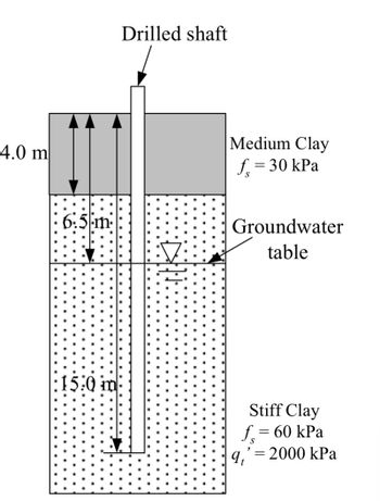
Transcribed Image Text:The image depicts a cross-sectional diagram of a drilled shaft embedded in different soil layers, designed for educational purposes.
### Description:
1. **Drilled Shaft**: A vertical structure is shown penetrating through two distinct soil layers.
2. **Soil Layers**:
- **Medium Clay Layer**:
- Thickness: 4.0 meters.
- Skin friction, \( f_s \): 30 kPa.
- **Stiff Clay Layer**:
- Thickness: 15.0 meters.
- Skin friction, \( f_s \): 60 kPa.
- Tip resistance, \( q_t' \): 2000 kPa.
3. **Groundwater Table**: Indicated within the stiff clay layer, showing the level at which groundwater is present.
### Key Components:
- **Arrows** indicate the depth measurements of each layer and the total penetration of the shaft.
- **Soil Properties**: Each clay type is characterized by its respective skin friction and, for stiff clay, also by tip resistance, crucial for engineering evaluations.
- **Dotted Region**: Represents the stiff clay layer, highlighting a typical representation style in geotechnical diagrams.
This diagram serves as an educational tool for understanding drilled shaft design and soil interaction in geotechnical engineering.

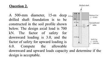
Transcribed Image Text:**Question 2.**
A 500-mm diameter, 15-m deep drilled shaft foundation is to be constructed in the soil profile shown below. The design axial load is 700 kN. The factor of safety for downward loading is 3.0, and the factor of safety for upward loading is 6.0. Compute the allowable downward and upward loads capacity and determine if the design is acceptable.
**Diagram Explanation:**
- **Drilled Shaft:** A cylindrical structure extending into the soil, 15 m deep.
- **Soil Layers:**
- **Medium Clay:**
- Depth: 4.0 m
- Shear strength \( f_s = 30 \, \text{kPa} \)
- **Stiff Clay:**
- Extends from 4.0 m to 15.0 m (11 m thick layer)
- Shear strength \( f_s = 60 \, \text{kPa} \)
- End bearing capacity \( q' = 2000 \, \text{kPa} \)
- **Groundwater Table:** Located 6.5 m below the surface.
Determine the downward and upward load capacities based on the factors of safety and soil properties provided.
Expert Solution
This question has been solved!
Explore an expertly crafted, step-by-step solution for a thorough understanding of key concepts.
This is a popular solution
Trending nowThis is a popular solution!
Step by stepSolved in 2 steps with 2 images

Knowledge Booster
Learn more about
Need a deep-dive on the concept behind this application? Look no further. Learn more about this topic, civil-engineering and related others by exploring similar questions and additional content below.Similar questions
- A standard penetration test has been conduted at a depth of 15 ft in an 8-inch diameter exploratory boring using a USA-style safety hammer and a standard sampler. This test produced an uncorrected N-value of 12. The soil inside the sampler was a fine-to-medium sand with Dsq = 0.6 mm. The vertical effective stress at this depth is 1100 lb/ft². Adjust the N- value as described in Class handout, then compute the relative density and classify the soil using Table 3.3.arrow_forwardShow solution with clear drawingsarrow_forwardDetermine the cohesionarrow_forward
Recommended textbooks for you

 Structural Analysis (10th Edition)Civil EngineeringISBN:9780134610672Author:Russell C. HibbelerPublisher:PEARSON
 Principles of Foundation Engineering (MindTap Cou...Civil EngineeringISBN:9781337705028Author:Braja M. Das, Nagaratnam SivakuganPublisher:Cengage Learning
 Fundamentals of Structural AnalysisCivil EngineeringISBN:9780073398006Author:Kenneth M. Leet Emeritus, Chia-Ming Uang, Joel LanningPublisher:McGraw-Hill Education
 Traffic and Highway EngineeringCivil EngineeringISBN:9781305156241Author:Garber, Nicholas J.Publisher:Cengage Learning


Structural Analysis (10th Edition)
Civil Engineering
ISBN:9780134610672
Author:Russell C. Hibbeler
Publisher:PEARSON

Principles of Foundation Engineering (MindTap Cou...
Civil Engineering
ISBN:9781337705028
Author:Braja M. Das, Nagaratnam Sivakugan
Publisher:Cengage Learning

Fundamentals of Structural Analysis
Civil Engineering
ISBN:9780073398006
Author:Kenneth M. Leet Emeritus, Chia-Ming Uang, Joel Lanning
Publisher:McGraw-Hill Education


Traffic and Highway Engineering
Civil Engineering
ISBN:9781305156241
Author:Garber, Nicholas J.
Publisher:Cengage Learning