Introductory Circuit Analysis (13th Edition)
13th Edition
ISBN: 9780133923605
Author: Robert L. Boylestad
Publisher: PEARSON
expand_more
expand_more
format_list_bulleted
Concept explainers
Question

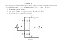
Transcribed Image Text:Question 1
In the single-phase diode rectifier circuit shown in Figure 1 and a constant de load current
Id = 10A, calculate, if v, is a sinusoidal voltage with V, = 120 V at 60 Hz,
i. the average output voltage
ii. rms values of input current and current through each diode
iii. the average power supplied to the load.
D14 D3 4
Expert Solution
This question has been solved!
Explore an expertly crafted, step-by-step solution for a thorough understanding of key concepts.
This is a popular solution
Trending nowThis is a popular solution!
Step by stepSolved in 3 steps with 3 images

Knowledge Booster
Learn more about
Need a deep-dive on the concept behind this application? Look no further. Learn more about this topic, electrical-engineering and related others by exploring similar questions and additional content below.Similar questions
- Design a single-phase full wave bridge rectifier with input voltage of 100v and inductive load of 10ohm and 40mH a. Show the waveform relation between the I/P and O/P b. Calculate the average O/P voltage c. Calculate the rms currentarrow_forwardTopic: Half Wave Rectificationarrow_forward9. The diodes in a bridge rectifier each have a maximum dc current rating of 2 A. What is the maximum value of the dc load current? 10. What is the PIV across each diode of a bridge rectifier with a secondary voltage of 20 V,rms?arrow_forward
- Tiguie Question 3 Figure 2 shows a center-tapped full wave rectifier circuit when a 100 V peak sine wave is applied to the primary winding. If the peak input in Figure 2 is changed to 220V draw the voltage waveforms across each half of the secondary winding and across Ri for TWO (2) complete input cycle voltage. Also determine the Vout, current through R. and PIV rating for each diode. Assume Dị and D2 are practical diode model. D 2:1 +100 V -- IN4001 V OV RL -100 V 10 k2 IN4001 Figure 2arrow_forwardWhat will be the out put of the D'Arsonval meters, if an average responding a.c meter of half-wave rectifier read (236 v), and true form foctor of input waveform is (114). *arrow_forwardIn the given Full Wave Center tapped Rectifier circuit, a step down transformer gives an RMS voltage as 110V/11-0-11 V is used with R₁ = 1 KQ. Assume diode as Germanium. D₁ a) Find Input Voltage Vin b) Find Peak Output Voltage. c) Find Average Output Voltage. d) Find Current through the load resistor. •ooooo 00000 CT 20-S D₂ R₁arrow_forward
- Q3/a/ what is the function of the inductance (L) in a single phase half wave thyristor ? b/ For 3 phase half wave rectifier source voltage is 100 sinwt with a = 40° find the Vav and draw the output voltage?arrow_forwardR₁ 54 R₂ D₁ ▷ Figure 1: Precision Rectifier 1. Characterize the relationship of input vs. output for the circuit in Figure 1. That is, find an expression for e. You can use the constant voltage drop model for the diodes. VIarrow_forwardPlease answer alll subparts i will like....arrow_forward
- A sine voltage trace displayed on a screen is shown in figure. The x axis is 1unit=40 ms and y axis is 1 unit=4 v; determine the frequency of the sine wave and plot the waveform if the same is applied to input of a full wave rectifier.arrow_forwardA full-wave bridge rectifier with a 100V rms sinusoidal input has a load resistor of 1 k. a. If silicon diodes are employed, what is the de voltage available at the load? b. Determine the required PIV rating of each diode. c. Find the maximum current through each diode during conduction. D.arrow_forward1. In a single-phase diode bridge rectifier, I-10A(rms), Is1=8A(rms), and DPF=0.9. Calculate Idistortion, %THD, and PF.arrow_forward
arrow_back_ios
SEE MORE QUESTIONS
arrow_forward_ios
Recommended textbooks for you
 Introductory Circuit Analysis (13th Edition)Electrical EngineeringISBN:9780133923605Author:Robert L. BoylestadPublisher:PEARSON
 Delmar's Standard Textbook Of ElectricityElectrical EngineeringISBN:9781337900348Author:Stephen L. HermanPublisher:Cengage Learning
 Programmable Logic ControllersElectrical EngineeringISBN:9780073373843Author:Frank D. PetruzellaPublisher:McGraw-Hill Education
 Fundamentals of Electric CircuitsElectrical EngineeringISBN:9780078028229Author:Charles K Alexander, Matthew SadikuPublisher:McGraw-Hill Education
 Electric Circuits. (11th Edition)Electrical EngineeringISBN:9780134746968Author:James W. Nilsson, Susan RiedelPublisher:PEARSON
 Engineering ElectromagneticsElectrical EngineeringISBN:9780078028151Author:Hayt, William H. (william Hart), Jr, BUCK, John A.Publisher:Mcgraw-hill Education,

Introductory Circuit Analysis (13th Edition)
Electrical Engineering
ISBN:9780133923605
Author:Robert L. Boylestad
Publisher:PEARSON

Delmar's Standard Textbook Of Electricity
Electrical Engineering
ISBN:9781337900348
Author:Stephen L. Herman
Publisher:Cengage Learning

Programmable Logic Controllers
Electrical Engineering
ISBN:9780073373843
Author:Frank D. Petruzella
Publisher:McGraw-Hill Education

Fundamentals of Electric Circuits
Electrical Engineering
ISBN:9780078028229
Author:Charles K Alexander, Matthew Sadiku
Publisher:McGraw-Hill Education

Electric Circuits. (11th Edition)
Electrical Engineering
ISBN:9780134746968
Author:James W. Nilsson, Susan Riedel
Publisher:PEARSON

Engineering Electromagnetics
Electrical Engineering
ISBN:9780078028151
Author:Hayt, William H. (william Hart), Jr, BUCK, John A.
Publisher:Mcgraw-hill Education,