Delmar's Standard Textbook Of Electricity
7th Edition
ISBN: 9781337900348
Author: Stephen L. Herman
Publisher: Cengage Learning
expand_more
expand_more
format_list_bulleted
Question

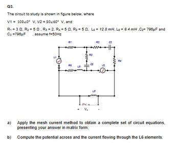
Transcribed Image Text:Q3.
The circuit to study is shown in figure below, where
V1 10040° V, V2=50260° V, and
R₁ =3Q, R₂ = 502, R3 = 2, R450, Rs 50, Ls = 12.8 mH. Ls = 6.4 mH,C2 796μF and
C3 =796µF . assume f=50Hz
V1
R1
R3
03
R2
R4
C2
RE
L5
Vx
a)
Apply the mesh current method to obtain a complete set of circuit equations,
presenting your answer in matrix form;
b) Compute the potential across and the current flowing through the L6 elements.
Expert Solution
This question has been solved!
Explore an expertly crafted, step-by-step solution for a thorough understanding of key concepts.
Step by stepSolved in 2 steps with 1 images

Knowledge Booster
Similar questions
- You are an electrician working in an industrial plant. You discover that the problem with a certain machine is a defective capacitor. The capacitor is connected to a 240-volt AC circuit. The information on the capacitor reveals that it has a capacitance value of 10 mF and a voltage rating of 240 VAC. The only 10-mF AC capacitor in the storeroom is marked with a voltage rating of 350 WVDC. Can this capacitor be used to replace the defective capacitor? Explain your answer.arrow_forward1.arrow_forwardFor the circuit below assuming an ideal switch, preform transient analysis to predict the voltage across resistor, R2 and plot the results. The inductor will have zero current as initial condition. L1 0.005 2 U1 100mH R1 1k V1 20Vdc R2 100arrow_forward
- Electric Circuits / Mutual Induction Topic: I need the solution to the questionarrow_forwardThe current through the diode in the circuit given in the Figure below when Vy = 0.7 V is? ww 8092 12V Select one a. 24.26 mA b. 13.09 mA c. 58.23 mA d. 40.13 mA 40-52 ww 3092 IDarrow_forwardA step down converter is operated with a duty cycle of k = 0.75. The input voltage is Vs = 20V, and the load is: L = 5mH, R = 1502. The minimum inductor current is I₁ = 0.1A. The maximum inductor current is: Select one: a. 1.9 A b. None of these OC. 0.9 A O d. 1.1 A Oe. 2 Aarrow_forward
- Q3] Design a circuit to produce an average voltage of 27V across a 102 load resistor from a 70V rms 50-Hz ac source. Verify your answer by the following: a) Draw the circuit. b) Draw to scale the waveforms for the input, output voltages and the current.arrow_forwardRMS VALUE OF CURRENT LOAD( NEED NEAT HANDWRITTEN SOLUTION ONLY OTHERWISE DOWNVOTE).arrow_forwardCan you help me solve this and explain clearly I saw some answers on chegg but I don’t understand it .arrow_forward
- Not Gradedarrow_forward2:50 1 LTE O Motor Warning Light Instructions PHYS&110-VHY-S21-PHYSNON-SCIMAJORSWLAB-.. STEP 3 Now add a red LED (D1 in the main schematic) in series with 500N of resistance (shown as R1 in the main schematic). How you choose to arrive at 5002 is up to you. SW1 PSB D2 D3 1N4007 5 V D1 Blue Red R3 10 ka R1 500 Q • What happens now when SW1 is (and the PSB is turned on)? • What happens if you turn the diode at D3 around? (Don't forget to turn it back the right way afterward.) • Why does this circuit use a diode at D3 instead of a pull-up resistor? (Meaning, what would happen if a resistor were used instead of the diode?) pressed ( Previous Next 14 Dashboard Calendar To Do Notifications Inboxarrow_forwardHalf-wave 50Hz sinusoidal uncontrolled rectifier circuit with a peak voltage value of 100V and a source inductance of 8mH is feeding a highly inductive load of 8A. The average value of the output voltage and power delivered are, respectively and what is the communication angle (u) Power Electronicsarrow_forward
arrow_back_ios
SEE MORE QUESTIONS
arrow_forward_ios
Recommended textbooks for you
 Delmar's Standard Textbook Of ElectricityElectrical EngineeringISBN:9781337900348Author:Stephen L. HermanPublisher:Cengage Learning

Delmar's Standard Textbook Of Electricity
Electrical Engineering
ISBN:9781337900348
Author:Stephen L. Herman
Publisher:Cengage Learning