
Introductory Circuit Analysis (13th Edition)
13th Edition
ISBN: 9780133923605
Author: Robert L. Boylestad
Publisher: PEARSON
expand_more
expand_more
format_list_bulleted
Related questions
Question
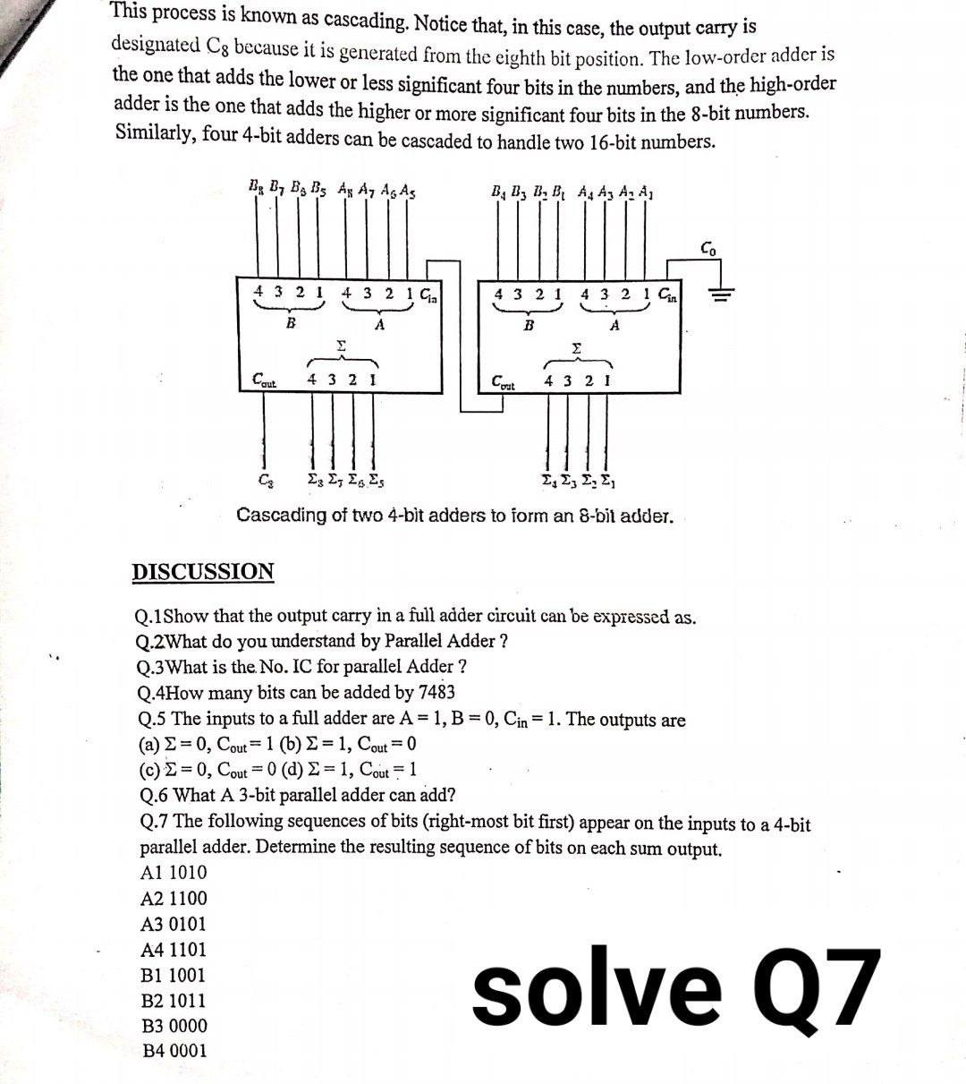

Transcribed Image Text:This process is known as cascading. Notice that, in this case, the output carry is
designated Cg because it is generated from the eighth bit position. The low-order adder is
the one that adds the lower or less significant four bits in the numbers, and the high-order
adder is the one that adds the higher or more significant four bits in the 8-bit numbers.
Similarly, four 4-bit adders can be cascaded to handle two 16-bit numbers.
Bg B, B3 B3 Ag A, Ag As
B, B, B, B A A3 A, A
Co
4 3 2 1 4 3 2 1 G
4 3 2
4 3 2 1 Cn
B
A
Cqut
4 3 2
Cat
4 3 2 1
E E, Eg Es
Σ, Σ Σ. Σ
Cascading of two 4-bit adders to form an 8-bit adder.
DISCUSSION
Q.1Show that the output carry in a full adder circuit can be expressed as.
Q.2What do you understand by Parallel Adder ?
Q.3What is the. No. IC for parallel Adder ?
Q.4How many bits can be added by 7483
Q.5 The inputs to a full adder are A 1, B 0, Cin = 1. The outputs are
( a) Σ-0, Cou1 (b) Σ = 1, Cou-0
(C)Σ-0, Cou-0 (d) Σ-1, Cout 1
Q.6 What A 3-bit parallel adder can add?
Q.7 The following sequences of bits (right-most bit first) appear on the inputs to a 4-bit
parallel adder. Determine the resulting sequence of bits on each sum output.
Al 1010
A2 1100
A3 0101
solve Q7
A4 1101
B1 1001
B2 1011
B3 0000
B4 0001
Expert Solution
This question has been solved!
Explore an expertly crafted, step-by-step solution for a thorough understanding of key concepts.

This is a popular solution

Trending nowThis is a popular solution!

Step by stepSolved in 2 steps with 2 images

Knowledge Booster


Learn more about
Need a deep-dive on the concept behind this application? Look no further. Learn more about this topic, electrical-engineering and related others by exploring similar questions and additional content below.Similar questions
- 1. Consider an 8:3 priority encoder with MSB having highest priority. If the input to this encoder is 10110001 (left most bit being MSB), then the output Y2 Y1 YO (Y2 is MSB) is 000 101 110 O 111 2. A 16:1 MUX cannot be implemented using two 4:1 MUXS & nine 2:1 MUXS eight 2:1 MUXS & two 4:1 MUXS four 4:1 MUXS & three 2:1 MUXS one 4:1 MUXS & twelve 2:1 MUXSarrow_forwardThe encoder is the inverse operation of a decoder. It generates the binary code corresponding to the input value. The following figure shows a block diagram of 8-to-3 encoder. There are eight inputs, i.e. D7 through D0, and three outputs (binary code), i.e. B2, B1 and B0. Answer the following questions. (Note: You should show all the steps) 1. If the input D7 is high (or “1”) and the other inputs are low (or “0”), what binary code does the encoder generate? 2. Draw the complete truth table of 8-to-3 encoder.arrow_forwardcan someone help me please and solve this questions with steps pleasearrow_forward
- add 25 and -20 (using 8-bit numbers) 8 and -19 (using 8-bit numbers)arrow_forwardDesign a 2-bit binary adder with carry. Your circuit should allow for two 2-bit binary input (a1a0 &b1b0) through switches and display the results of the addition in decimal format using the 7-segmentdisplay.arrow_forwardElectrical Engineering Verilog Design N-bit binary counter which counts the number from 0 to 2N-1. After reaching to maximum count i.e. 2N-1, it again starts the count from 0. i. Write the description of the counter in Verilog ii. Generate the design from the listing ii. Produce the waveforms of the counterarrow_forward
- Please do this, urgently needed.arrow_forward1. Gray code to Binary converter: Gray code is one of the codes used in digital systems. It has the advantage over binary numbers that only one bit in the code word changes when going from one number to the next. (See Table 1). Design a combinational circuit with 4 inputs and 4 outputs that converts a four- bit gray code number into an equivalent four-bit Binary number. Use Karnaugh map technique for simplification. Use LogicWorks for pre-lab demonstrations. Select the library "7400dev.clf* in the Parts Palette and then select the XOR chip 74-86. This would give you a set of 4 XOR's as shown in Fig. 1, just like the hardware chip 74-86. You could use as many as needed from these XOR gates in your design. Get back to ALL LIBRARIES and select switches for the inputs and Binary Probes as indicators of the outputs. Verify your design in the pre-Lab. During the Lab construct the circuit and verify its operations.arrow_forwardComplete the Hamming code below for the given 4-bit hex values. Insert the ODD parity bits into positions 1, 2, and 4. For this problem, P means POSITION, not parity. The parity bit in P1 checks bits P1, P3, P5, and P7. The parity bit in P2 checks bits P2, P3, P6, and P7. The parity bit in P4 checks bits P4, P5, P6, and P7. Hex 0: 7: A: P1 P2 P3 0 P4 P5 0 1 ? P6 0 1 ? P7 0 1 ?arrow_forward
- Digital logic design Solve it with drawing and simulation lab I need them both to have the full solution. And thanks Design counter that counts from 00 to 59, using the IC 74LS90 ripple counter and use two 7 segment display to display the result count. You can also use 7447 binary to 7-segment Display Decoder.arrow_forward5. In the circuit implementation of an 8-bit adder, explain why the carry bit connection of the least- significant bit is connected to ground. Explain in words what values for A, B, C, D, E will cause a 1 to appear at point X. The circuit below uses a 5-input AND gate. Draw the equivalent circuit using only 2-input gates.arrow_forwardFor a 4-bit parallel adder, if the carry-in is connected to a logical HIGH, the result is O a. The carry-out is ignored b. The same as if the carry-in is tied LOW since / the least significant carry-in is ignored O C. A one will be added to the final result o d. That carry-out will always be HIGHarrow_forward
arrow_back_ios
SEE MORE QUESTIONS
arrow_forward_ios
Recommended textbooks for you
- Introductory Circuit Analysis (13th Edition)Electrical EngineeringISBN:9780133923605Author:Robert L. BoylestadPublisher:PEARSON
 Delmar's Standard Textbook Of ElectricityElectrical EngineeringISBN:9781337900348Author:Stephen L. HermanPublisher:Cengage Learning
 Programmable Logic ControllersElectrical EngineeringISBN:9780073373843Author:Frank D. PetruzellaPublisher:McGraw-Hill Education
  Fundamentals of Electric CircuitsElectrical EngineeringISBN:9780078028229Author:Charles K Alexander, Matthew SadikuPublisher:McGraw-Hill Education
 Electric Circuits. (11th Edition)Electrical EngineeringISBN:9780134746968Author:James W. Nilsson, Susan RiedelPublisher:PEARSON
 Engineering ElectromagneticsElectrical EngineeringISBN:9780078028151Author:Hayt, William H. (william Hart), Jr, BUCK, John A.Publisher:Mcgraw-hill Education,
Introductory Circuit Analysis (13th Edition)
Electrical Engineering
ISBN:9780133923605
Author:Robert L. Boylestad
Publisher:PEARSON
Delmar's Standard Textbook Of Electricity
Electrical Engineering
ISBN:9781337900348
Author:Stephen L. Herman
Publisher:Cengage Learning
Programmable Logic Controllers
Electrical Engineering
ISBN:9780073373843
Author:Frank D. Petruzella
Publisher:McGraw-Hill Education
Fundamentals of Electric Circuits
Electrical Engineering
ISBN:9780078028229
Author:Charles K Alexander, Matthew Sadiku
Publisher:McGraw-Hill Education
Electric Circuits. (11th Edition)
Electrical Engineering
ISBN:9780134746968
Author:James W. Nilsson, Susan Riedel
Publisher:PEARSON
Engineering Electromagnetics
Electrical Engineering
ISBN:9780078028151
Author:Hayt, William H. (william Hart), Jr, BUCK, John A.
Publisher:Mcgraw-hill Education,