
Introductory Circuit Analysis (13th Edition)
13th Edition
ISBN: 9780133923605
Author: Robert L. Boylestad
Publisher: PEARSON
expand_more
expand_more
format_list_bulleted
Related questions
Question
Please do this, urgently needed.
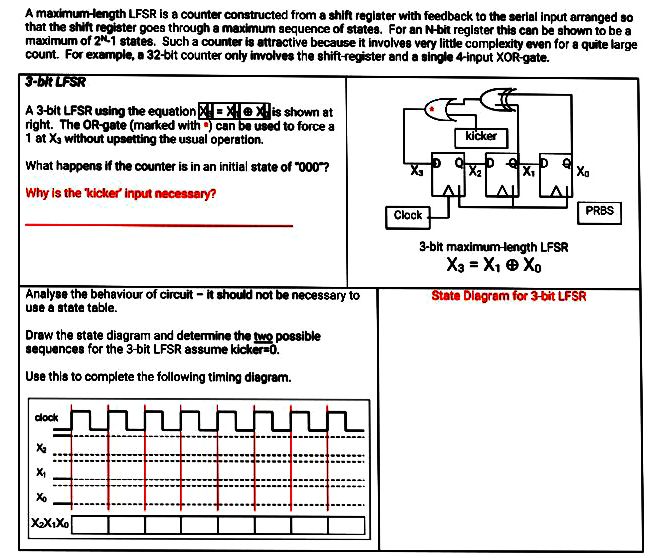

Transcribed Image Text:A maximum-length LFSR is a counter constructed from a shift register with feedback to the serial input arranged so
that the shift register goes through a maximum sequence of states. For an N-bit reglster this can be shown to be a
maximum of 21 states. Such a counter is attractive because it involves very little complexity even for a quite large
count. For example, a 32-bit counter only involves the shift-register and a single 4-input XOR-gate.
3-biR LFSR
A 3-bit LFSR using the equation!X!exlis shown at
right. The OR-gate (marked with ) can be used to force a
1 at Xa without upsetting the usual operation.
kicker
What happens if the counter is in an initial state of "000?
Xa
Why is the kicker input necessary?
Clock
PRBS
3-bit maximum-length LFSR
X3 = X, e Xo
Analyse the behaviour of circuit - it should not be necessary to
use a state table.
State Dlagram for 3-bit LFSR
Draw the state diagram and determine the two possible
sequences for the 3-bit LFSR assume kicker=0.
Use this to complete the following timing diagram.
dock
XX,Xo
Expert Solution
This question has been solved!
Explore an expertly crafted, step-by-step solution for a thorough understanding of key concepts.

Step by stepSolved in 5 steps with 5 images

Knowledge Booster


Learn more about
Need a deep-dive on the concept behind this application? Look no further. Learn more about this topic, electrical-engineering and related others by exploring similar questions and additional content below.Similar questions
- What is meant by Power Conversion Efficiency.arrow_forward2. Describe what you understand by overcurrents and indicate the protection devices that can be used for this purpose. What do you know about selectivity and parity between protections? Justify your answer.arrow_forwardRefer to the National Electrical Code® or the working drawings when necessary. Where applicable, responses should be written in complete sentences. For problems 1 and 2, six luminaires, similar to Style E used in the Commercial Building, are to be installed in a room that is 12 ft x 18 ft (~3.7 m x ~5.5 m) with a 9 ft (2.8 m) floor-to-ceiling height. The spacing ratio for the luminaire is 1:0. 1. The maximum distance that the luminaires can be separated and achieve uniform illuminance is ft ( m). For problems 2-5, two luminaires, 8 ft (2.5 m) and 4 ft (1.2 m) in length with dimensions as shown in Figure 15-7, are to be installed in tandem (end to end). The end of the long luminaire is to be 2 ft (600 mm) from the wall. 2. The center of the outlet box should be roughed in at ft ( m) from the wall. 3. The first support should be installed at the wall. ft ( m) from 4. The second support should be installed at from the wall. ft ( m) 5. The final support should be installed at the wall. ft…arrow_forward
Recommended textbooks for you
- Introductory Circuit Analysis (13th Edition)Electrical EngineeringISBN:9780133923605Author:Robert L. BoylestadPublisher:PEARSON
 Delmar's Standard Textbook Of ElectricityElectrical EngineeringISBN:9781337900348Author:Stephen L. HermanPublisher:Cengage Learning
 Programmable Logic ControllersElectrical EngineeringISBN:9780073373843Author:Frank D. PetruzellaPublisher:McGraw-Hill Education
  Fundamentals of Electric CircuitsElectrical EngineeringISBN:9780078028229Author:Charles K Alexander, Matthew SadikuPublisher:McGraw-Hill Education
 Electric Circuits. (11th Edition)Electrical EngineeringISBN:9780134746968Author:James W. Nilsson, Susan RiedelPublisher:PEARSON
 Engineering ElectromagneticsElectrical EngineeringISBN:9780078028151Author:Hayt, William H. (william Hart), Jr, BUCK, John A.Publisher:Mcgraw-hill Education,
Introductory Circuit Analysis (13th Edition)
Electrical Engineering
ISBN:9780133923605
Author:Robert L. Boylestad
Publisher:PEARSON
Delmar's Standard Textbook Of Electricity
Electrical Engineering
ISBN:9781337900348
Author:Stephen L. Herman
Publisher:Cengage Learning
Programmable Logic Controllers
Electrical Engineering
ISBN:9780073373843
Author:Frank D. Petruzella
Publisher:McGraw-Hill Education
Fundamentals of Electric Circuits
Electrical Engineering
ISBN:9780078028229
Author:Charles K Alexander, Matthew Sadiku
Publisher:McGraw-Hill Education
Electric Circuits. (11th Edition)
Electrical Engineering
ISBN:9780134746968
Author:James W. Nilsson, Susan Riedel
Publisher:PEARSON
Engineering Electromagnetics
Electrical Engineering
ISBN:9780078028151
Author:Hayt, William H. (william Hart), Jr, BUCK, John A.
Publisher:Mcgraw-hill Education,