Structural Analysis
6th Edition
ISBN: 9781337630931
Author: KASSIMALI, Aslam.
Publisher: Cengage,
expand_more
expand_more
format_list_bulleted
Question

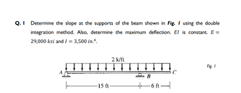
Transcribed Image Text:Q. Determine the slope at the supports of the beam shown in Fig. I using the double
integration method. Also, determine the maximum deflection. El is constant. E =
29,000 ksi and I = 3,500 in.4.
2 k/ft
↓ ↓ ↓ ↓ ↓
Fig. 1
A
C
B
-15 ft-
-6 ft-
Expert Solution
This question has been solved!
Explore an expertly crafted, step-by-step solution for a thorough understanding of key concepts.
Step by stepSolved in 2 steps with 3 images

Knowledge Booster
Similar questions
- HW 2: Determine the deflection at point C of the beam shown in Fig. below by the virtual work method. ↓↓ 2 k/ft 30 ft El constant E = 29,000 ksi I= 2,000 in.4 B 10 ft- 12 k C Ac = 0.194 in. ↑arrow_forwardUse the conjugate beam method to determine the slope and deflection at point D of the beam shown.arrow_forward2. Determine the maximum deflection of the simply supported beam using double integration method. E = 200 GPa and l=65.0x106 mm4. %3D 24 kN 18 kN/m A B |-1.5 m→-1.5 m- 3 marrow_forward
- Double Integration Method Determine the slope and deflection at B and the maximum deflection for the beam. EI is constant.arrow_forward2. USE THE CONJUGATE BEAM METHOD TO DETERMINE THE SLOPES AT END A AND THE DEFLECTIONS AT POINTS B OF THE BEAM SHOWN BELOW. -5 m 120 kN B L = 15 m El constant 120 kN с |—–3 m -3arrow_forward6. Given the beam loaded as shown, determine the deflection at the midspan. Use Conjugate Beam Method. 270 kN 45 kN/m A В 3 m 3 m 3 m El = constant E = 200 GPa I = 1665x10°mm4arrow_forward
- Q. 5 Determine the deflections at B and C for the beam shown in Fig. 5 using the moment- area method. Also, determine the slope at D. El is constant. E = 20,000 ksi and I = 31500 in.4. 1.5 k/ft 30 k ↓↓↓↓ Fig. 5 A B C 6 ft 4 ft -- -5 ft-arrow_forwardshow area moment diagramarrow_forward1. Determine the slope and deflection at point B of the beam shown by the double integration method. (Quiz 1) 50 kN-m A -4 m. El = constant E = 70 GPa I = 164 (106) mmarrow_forward
- Determine the slope and deflection at D for the beam shown by the conjugate beam method. EI is constant.arrow_forwardHW 2: Determine the horizontal and vertical components of the deflection at joint B of the truss shown in Fig. (a) by the virtual work method. 35 kN] 84 kN 4m 3m EA constant E = 200 GPa A = 1,200 mm² (a) IT I 4m ABH = 0.35 mm → ABV = 3.32 mm ↓ Ans. Ans.arrow_forwardThe beam shown below is subjected to two 4 kN concentrated loads located 1.5 meters from each support. The bending moment diagram for the beam is plotted. Using the moment-area method, determine the deflection at point С. (A Assume E=200GPA, I=4×106 mm4) 4 kN 4 kN VD А В D00. 1.5 m 3 m 1.5 m 6 Bending Moment Diagram (kN.m) +arrow_forward
arrow_back_ios
SEE MORE QUESTIONS
arrow_forward_ios
Recommended textbooks for you

 Structural Analysis (10th Edition)Civil EngineeringISBN:9780134610672Author:Russell C. HibbelerPublisher:PEARSON
 Principles of Foundation Engineering (MindTap Cou...Civil EngineeringISBN:9781337705028Author:Braja M. Das, Nagaratnam SivakuganPublisher:Cengage Learning
 Fundamentals of Structural AnalysisCivil EngineeringISBN:9780073398006Author:Kenneth M. Leet Emeritus, Chia-Ming Uang, Joel LanningPublisher:McGraw-Hill Education
 Traffic and Highway EngineeringCivil EngineeringISBN:9781305156241Author:Garber, Nicholas J.Publisher:Cengage Learning


Structural Analysis (10th Edition)
Civil Engineering
ISBN:9780134610672
Author:Russell C. Hibbeler
Publisher:PEARSON

Principles of Foundation Engineering (MindTap Cou...
Civil Engineering
ISBN:9781337705028
Author:Braja M. Das, Nagaratnam Sivakugan
Publisher:Cengage Learning

Fundamentals of Structural Analysis
Civil Engineering
ISBN:9780073398006
Author:Kenneth M. Leet Emeritus, Chia-Ming Uang, Joel Lanning
Publisher:McGraw-Hill Education


Traffic and Highway Engineering
Civil Engineering
ISBN:9781305156241
Author:Garber, Nicholas J.
Publisher:Cengage Learning