Introductory Circuit Analysis (13th Edition)
13th Edition
ISBN: 9780133923605
Author: Robert L. Boylestad
Publisher: PEARSON
expand_more
expand_more
format_list_bulleted
Concept explainers
Question
thumb_up100%
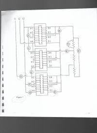
Answerthe follonwing based on the 3-phase configuratio in figure 7, worksshet4.
What is Ammeter A4 is measuring - A- line current, B- Phase current, C- neither "a" nor "b", D- both "a" and "b"
Ammeter A5 is measuring - A- line current, B- phase current, C- neither "a" nor "b", D- both "a" and "b".
Ammeter A6 is measuring - A line current, B- phase current, C-neither "a" nor "b"., D- both 'A' and "b"

Transcribed Image Text:Certainly! Below is the transcription and explanation suitable for an educational website.
---
**Transcription and Explanation of Figure 7:**
The diagram illustrates the configuration of a multi-phase electrical circuit system. This system involves several components labeled A1 to A6, V1 to V4, and T5. The schematic diagram is divided into sections connected by lines that represent electrical wiring.
### Detailed Explanation:
**Three-Phase Power Input:**
- The top left part of the diagram shows the three-phase power input labeled L1, L2, and L3. These lines supply power to the system.
**Vertical Components:**
- **V1, V2, V3:** These are voltage measurement points connected to the horizontal bus lines in the diagram. They are arranged vertically and are connected to H1 through H4 inputs, indicating their involvement in the measurement or transmission of voltage or current.
**Horizontal Components:**
- **Inputs H1 to H4:** These input channels are linked to vertical connectors and are subsequently linked to outputs X1 to X4.
- **Outputs X1 to X4:** These are the output terminals of the system, possibly indicating relays or other control outputs. Each set of inputs (H1 to H4) is connected to a corresponding set of outputs (X1 to X4).
**Central Connections:**
- **A1, A2, A3, A4, A5, A6:** These labels likely denote connection points or components within the system, such as amplifiers, sensors, or control modules.
- **T5:** This might represent a transformer or another type of electrical component crucial for managing or transforming voltage or current within the system.
**Additional Elements:**
- **Resistors and Coils:** The diagram includes standard symbols for resistors and coils (present near the A5 label), suggesting additional control or regulation within the circuit, potentially for impedance matching or filtering.
The layout and labeling suggest a carefully planned design for monitoring and controlling electrical outputs across multiple phases.
---
This explanation covers the technical components and the general working of the circuit as shown in Figure 7.
Expert Solution
This question has been solved!
Explore an expertly crafted, step-by-step solution for a thorough understanding of key concepts.
This is a popular solution
Trending nowThis is a popular solution!
Step by stepSolved in 2 steps

Knowledge Booster
Learn more about
Need a deep-dive on the concept behind this application? Look no further. Learn more about this topic, electrical-engineering and related others by exploring similar questions and additional content below.Similar questions
- 3. What is the effect as more inductors are added in parallel to a circuit? A. Increased total inductance. B. Increased total inductive reactance. C. Increased total resistance. D. Increased total circuit current.arrow_forwardThree inductors are connected in series to a 480-volt, 60 Hz power source. The current flow in the circuit is 0.509 amp. Inductor #1 has an inductance of 1.3 henry, and inductor #2 has an inductance of 0.75 henry. What is the inductance of inductor #3?arrow_forwardwhat is the maximum output voltage the circuit can produce? (without regard to phase)arrow_forward
- 4. A resistor and inductor are connected in parallel to a 277 volt, 60 Hz line. The resis- 12. tor has a current of 12 amperes flowing through it, and the inductor has a current flow of 8 amperes flowing through it. What is the total current flow in the circuit? m bas vlaquaarrow_forwardA capacitor and resistor are connected in series. The resistor has a resistance of 26 ohms and the capacitor has a capacitive resistance of 16 ohms. What is the impedance of the circuit?arrow_forward
arrow_back_ios
arrow_forward_ios
Recommended textbooks for you
 Introductory Circuit Analysis (13th Edition)Electrical EngineeringISBN:9780133923605Author:Robert L. BoylestadPublisher:PEARSON
 Delmar's Standard Textbook Of ElectricityElectrical EngineeringISBN:9781337900348Author:Stephen L. HermanPublisher:Cengage Learning
 Programmable Logic ControllersElectrical EngineeringISBN:9780073373843Author:Frank D. PetruzellaPublisher:McGraw-Hill Education
 Fundamentals of Electric CircuitsElectrical EngineeringISBN:9780078028229Author:Charles K Alexander, Matthew SadikuPublisher:McGraw-Hill Education
 Electric Circuits. (11th Edition)Electrical EngineeringISBN:9780134746968Author:James W. Nilsson, Susan RiedelPublisher:PEARSON
 Engineering ElectromagneticsElectrical EngineeringISBN:9780078028151Author:Hayt, William H. (william Hart), Jr, BUCK, John A.Publisher:Mcgraw-hill Education,

Introductory Circuit Analysis (13th Edition)
Electrical Engineering
ISBN:9780133923605
Author:Robert L. Boylestad
Publisher:PEARSON

Delmar's Standard Textbook Of Electricity
Electrical Engineering
ISBN:9781337900348
Author:Stephen L. Herman
Publisher:Cengage Learning

Programmable Logic Controllers
Electrical Engineering
ISBN:9780073373843
Author:Frank D. Petruzella
Publisher:McGraw-Hill Education

Fundamentals of Electric Circuits
Electrical Engineering
ISBN:9780078028229
Author:Charles K Alexander, Matthew Sadiku
Publisher:McGraw-Hill Education

Electric Circuits. (11th Edition)
Electrical Engineering
ISBN:9780134746968
Author:James W. Nilsson, Susan Riedel
Publisher:PEARSON

Engineering Electromagnetics
Electrical Engineering
ISBN:9780078028151
Author:Hayt, William H. (william Hart), Jr, BUCK, John A.
Publisher:Mcgraw-hill Education,