
Principles of Foundation Engineering (MindTap Course List)
8th Edition
ISBN: 9781305081550
Author: Braja M. Das
Publisher: Cengage Learning
expand_more
expand_more
format_list_bulleted
Related questions
Concept explainers
Question
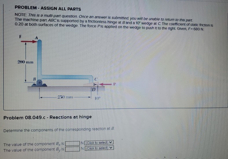

Transcribed Image Text:PROBLEM - ASSIGN ALL PARTS
NOTE: This is a multi-part question. Once an answer is submitted, you will be unable to return to this part.
The machine part ABC is supported by a frictionless hinge at B and a 10° wedge at C. The coefficient of static friction is
0.20 at both surfaces of the wedge. The force Pis applied on the wedge to push it to the right. Given, F= 680 N.
F
200 mm
B
-250 mm
Problem 08.049.c - Reactions at hinge
D
The value of the component By Is
The value of the component By Is [
10°
Determine the components of the corresponding reaction at B
N (Click to select)
N(Click to select)
Expert Solution
This question has been solved!
Explore an expertly crafted, step-by-step solution for a thorough understanding of key concepts.

This is a popular solution

Trending nowThis is a popular solution!

Step by stepSolved in 3 steps with 3 images

Knowledge Booster


Learn more about
Need a deep-dive on the concept behind this application? Look no further. Learn more about this topic, civil-engineering and related others by exploring similar questions and additional content below.Similar questions
- Refer to Figure P6.4. A strip load of q = 900 lb/ft2 is applied over a width B = 36 ft. Determine the increase in vertical stress at point A located z = 15 ft below the surface. Given: x = 27 ft. Figure P6.4arrow_forwardBourdon-type pressure gauges are used in thousands of applications. A deadweight tester is a device that is used to calibrate pressure gauges. Investigate the operation of a deadweight pressure tester. Write a brief report to discuss your findings.arrow_forwardA structural member with a rectangular cross section as shown in the accompanying figure is used to support a load of 2500 N. What type of material do you recommend be used to carry the load safely? Base your calculations on the yield strength and a factor of safety of 2.0.arrow_forward
- Refer to Figure 10.43. A strip load of q = 1450 lb/ft2 is applied over a width with B = 48 ft. Determine the increase in vertical stress at point A located z = 21 ft below the surface. Given x = 28.8 ft. Figure 10.43arrow_forwardTwo line loads q1 and q2 of infinite lengths are acting on top of an elastic medium, as shown in Figure P8.6. Find the vertical stress increase at A.arrow_forwardA 10 cm long rectangular bar (when subjected to a tensile load) deforms by 0.1 mm. Calculate the normal strain.arrow_forward
- A column in a building is subjected to the following load effects: 9 kips compression from dead load 5 kips compression from roof live load 6 kips compression from snow 7 kips compression from 3 inches of rain accumulated on the roof 8 kips compression from wind a. If lead and resistance factor design is used, determine the factored load (required strength) to be used in the design of the column. Which AISC load combination controls? b. What is the required design strength of the Column? c. What is the required nominal strength of the column for a resistance factor of 0.90? d. If allowable strength design is used, determine the required load capacity (required strength) to be used in the design of the column. Which AISC load combination controls? e. What is the required nominal strength of the column for a safety factor of 1.67?arrow_forwardThe data in Table 1.5.3 were obtained from a tensile test of a metal specimen with a rectangular cross section of 0.2011in.2 in area and a gage length (the length over which the elongation is measured) of 2.000 inches. The specimen was not loaded to failure. a. Generate a table of stress and strain values. b. Plot these values and draw a best-fit line to obtain a stress-strain curve. c. Determine the modulus of elasticity from the slope of the linear portion of the curve. d. Estimate the value of the proportional limit. e. Use the 0.2 offset method to determine the yield stress.arrow_forwardCompare the engineering and true secant elastic moduli for the natural rubber in Example Problem 6.2 at an engineering strain of 6.0. Assume that the deformation is all elastic.arrow_forward
arrow_back_ios
arrow_forward_ios
Recommended textbooks for you
- Principles of Foundation Engineering (MindTap Cou...Civil EngineeringISBN:9781305081550Author:Braja M. DasPublisher:Cengage Learning
 Engineering Fundamentals: An Introduction to Engi...Civil EngineeringISBN:9781305084766Author:Saeed MoaveniPublisher:Cengage Learning
 Residential Construction Academy: House Wiring (M...Civil EngineeringISBN:9781285852225Author:Gregory W FletcherPublisher:Cengage Learning
  Fundamentals of Geotechnical Engineering (MindTap...Civil EngineeringISBN:9781305635180Author:Braja M. Das, Nagaratnam SivakuganPublisher:Cengage Learning
 Steel Design (Activate Learning with these NEW ti...Civil EngineeringISBN:9781337094740Author:Segui, William T.Publisher:Cengage Learning
 Materials Science And Engineering PropertiesCivil EngineeringISBN:9781111988609Author:Charles GilmorePublisher:Cengage Learning
Principles of Foundation Engineering (MindTap Cou...
Civil Engineering
ISBN:9781305081550
Author:Braja M. Das
Publisher:Cengage Learning
Engineering Fundamentals: An Introduction to Engi...
Civil Engineering
ISBN:9781305084766
Author:Saeed Moaveni
Publisher:Cengage Learning
Residential Construction Academy: House Wiring (M...
Civil Engineering
ISBN:9781285852225
Author:Gregory W Fletcher
Publisher:Cengage Learning
Fundamentals of Geotechnical Engineering (MindTap...
Civil Engineering
ISBN:9781305635180
Author:Braja M. Das, Nagaratnam Sivakugan
Publisher:Cengage Learning
Steel Design (Activate Learning with these NEW ti...
Civil Engineering
ISBN:9781337094740
Author:Segui, William T.
Publisher:Cengage Learning
Materials Science And Engineering Properties
Civil Engineering
ISBN:9781111988609
Author:Charles Gilmore
Publisher:Cengage Learning