Introductory Circuit Analysis (13th Edition)
13th Edition
ISBN: 9780133923605
Author: Robert L. Boylestad
Publisher: PEARSON
expand_more
expand_more
format_list_bulleted
Question

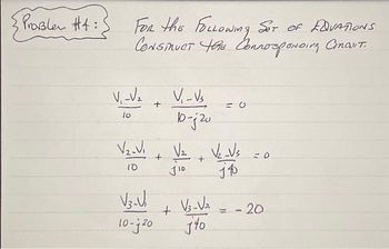
Transcribed Image Text:Problem #4:
FOR thE FOLLOWING SET OF EQVATIONS
CONSTRUCT the Conrosponding Cincit.
бот
V₁-V₂ + V₁-V₁.
10-j 20
lo
V₂-V₁
10
V3.V.
10-j 20
+
V₂ V₂ Vs
+
J10
14
+
V3-√₂
jto
=0
- 20
Expert Solution
This question has been solved!
Explore an expertly crafted, step-by-step solution for a thorough understanding of key concepts.
Step by stepSolved in 3 steps with 3 images

Knowledge Booster
Learn more about
Need a deep-dive on the concept behind this application? Look no further. Learn more about this topic, electrical-engineering and related others by exploring similar questions and additional content below.Similar questions
- SOLVE IN ONE HOUR I WILL GIVE UPVOTE THANKSarrow_forwardWhich of the following correctly expresses the magnitude of the transfer function for the series RC low-pass filter? 1/RC -w2+ (6 1/RC w² + (- -)² 1 RC √w². 1 RC 1 RC √₁²+(-_=_=1² RC 1+RC RC RCarrow_forwardQ5:-What are the Properties of Z- * ? Transform? Wrire one Examplearrow_forward
- Needed to be solved correctly in 10 minutes in the order to get positive feedback please show me neat and clean work for it By hand solution neededarrow_forwardConsider a circuit where an ideal inductor L=0.144H is connected in parallel to a resistor R=1.00kΩ. This combination is connected in series with a capacitor C=3.67e-07F. This combination in connected to a power supply source of frequency f=3.4kHz. To study this circuit you need to draw a phasor diagram. Note the sum of the current phasors through the resistor and the inductor must be equal to the phasor representing the current through the capacitor (i.e. the total current). You should draw the phasor for the current through the capacitor on the horizontal axis, since this is also the total current delivered by the supply. The angle between this phasor and that of the power supply represents the phase angle ?.Note that the voltage across the inductor equals the voltage across the resistor since they connected parallel to each other. Furthermore the sum of the phasors representing the currents through the inductor and the resistor equals the phasor representing the current through the…arrow_forwardFor the circuit shown, what is the Thevenin equivalent voltage, VT? j2 n ll j4 N ll 36445° V -j5 N O 31.05445.0° V 21.95Z11.5° V 21.9545.0° V O 31.05/11.5° Varrow_forward
- Fast pls solve this question correctly in 5 min pls I will give u like for sure Sub Convert the equation given in rectangular form into polar form. y=6arrow_forwardA given impedance draws 5 A from a 120 V, 60 Hz source. The current through the impedance lags the voltage across it by 60°. What is the total current drawn from the source when 100 µF capacitor is connected in parallel with the given impedance?arrow_forwardProblem #4: FOR the FOLLOWING SET OF EQVATIONS CONSTRUCT this Connosponding Cincuit. V₁-V₂ V₂_Vi 10 + V3-V₁ 10-20 + V₁-V3 10-j 20 V₂ J10 + + V3-√₂ jto V₂ _Vs j 40 -20.arrow_forward
- Before to = Os the key stayed open and there was a steady state in the following circuit. At to the key was toggled (switched to "close" position). Find and draw waveform u(t) in the follwing circuit. Data: E = 6 V, J = 4mA, R1 = 2 k, R2 = 1 kſN, R3 = 3 kN, C = 4 µF. R2 R1 to , u(t)R3 Earrow_forwardFiAd the 2-Transformof the sequence andih OC 3arrow_forwardhelp me!!!arrow_forward
arrow_back_ios
SEE MORE QUESTIONS
arrow_forward_ios
Recommended textbooks for you
 Introductory Circuit Analysis (13th Edition)Electrical EngineeringISBN:9780133923605Author:Robert L. BoylestadPublisher:PEARSON
 Delmar's Standard Textbook Of ElectricityElectrical EngineeringISBN:9781337900348Author:Stephen L. HermanPublisher:Cengage Learning
 Programmable Logic ControllersElectrical EngineeringISBN:9780073373843Author:Frank D. PetruzellaPublisher:McGraw-Hill Education
 Fundamentals of Electric CircuitsElectrical EngineeringISBN:9780078028229Author:Charles K Alexander, Matthew SadikuPublisher:McGraw-Hill Education
 Electric Circuits. (11th Edition)Electrical EngineeringISBN:9780134746968Author:James W. Nilsson, Susan RiedelPublisher:PEARSON
 Engineering ElectromagneticsElectrical EngineeringISBN:9780078028151Author:Hayt, William H. (william Hart), Jr, BUCK, John A.Publisher:Mcgraw-hill Education,

Introductory Circuit Analysis (13th Edition)
Electrical Engineering
ISBN:9780133923605
Author:Robert L. Boylestad
Publisher:PEARSON

Delmar's Standard Textbook Of Electricity
Electrical Engineering
ISBN:9781337900348
Author:Stephen L. Herman
Publisher:Cengage Learning

Programmable Logic Controllers
Electrical Engineering
ISBN:9780073373843
Author:Frank D. Petruzella
Publisher:McGraw-Hill Education

Fundamentals of Electric Circuits
Electrical Engineering
ISBN:9780078028229
Author:Charles K Alexander, Matthew Sadiku
Publisher:McGraw-Hill Education

Electric Circuits. (11th Edition)
Electrical Engineering
ISBN:9780134746968
Author:James W. Nilsson, Susan Riedel
Publisher:PEARSON

Engineering Electromagnetics
Electrical Engineering
ISBN:9780078028151
Author:Hayt, William H. (william Hart), Jr, BUCK, John A.
Publisher:Mcgraw-hill Education,