Introductory Circuit Analysis (13th Edition)
13th Edition
ISBN: 9780133923605
Author: Robert L. Boylestad
Publisher: PEARSON
expand_more
expand_more
format_list_bulleted
Concept explainers
Question
thumb_up100%

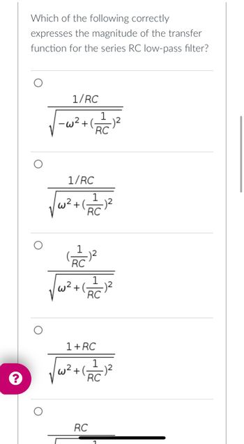
Transcribed Image Text:Which of the following correctly
expresses the magnitude of the transfer
function for the series RC low-pass filter?
1/RC
-w2+ (6
1/RC
w² + (- -)²
1
RC
√w².
1
RC
1
RC
√₁²+(-_=_=1²
RC
1+RC
RC
RC

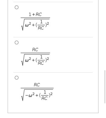
Transcribed Image Text:1+RC
√√w² + (21/1²
RC
w2
RC
+(
1
RC
RC
-w2
+(
RC
Expert Solution
This question has been solved!
Explore an expertly crafted, step-by-step solution for a thorough understanding of key concepts.
Step by stepSolved in 3 steps with 3 images

Knowledge Booster
Learn more about
Need a deep-dive on the concept behind this application? Look no further. Learn more about this topic, electrical-engineering and related others by exploring similar questions and additional content below.Similar questions
- (c) Design a series RLC bandpass filter with cutoff frequencies fc₁ = 1 KHz, fcz = 20 KHz, using a 100 resistor. Draw the circuit and label all the components, including circuit values, including input and output. Also draw the magnitude and phase plots for the filter. Amplitude [dB] 50 40 30- Phase [°] 10 of- -10... -20... -30- -40- -50 0.1 180 135 90 C 45 of -45- -90 -135- -180 0.1 1 1 10 10 100 100 1000 1000 10,000 Freq. (Hz) 10,000 Freq. (Hz)arrow_forwardan ideal low pass filter with a cutoff frequency of 46KHZ, is fed by the periodic signal shown in the figure, determine. Plot the spectrum of the periodic signalarrow_forward(a)Design a series RC high-pass filter with a cutoff frequency fc = 1 KHz, using a 20 µF capacitor. Draw the circuit and label all the components, including circuit elements values, input and output. Also draw the magnitude and phase plots for the filter. Amplitude [dB] 50 40 30 20 10 Phase [°] of -10- -20 -30--- -40- -50 0.1 180 135 90 C 45 of -45- -90 -135 -180 01 1 1 10 10 100 100 1000 1000 10,000 Freq. (Hz) 10,000 Freq. (Hz)arrow_forward
- Please help mearrow_forwardC4 10n U1 R1 R2 Vou 10k 10k V1 C3 10n AC 1 .ac dec 50 10 10k .lib opamp.sub Determine the resonant frequency fo in Hz of the lowpass filter shown above.arrow_forward1. Draw the complete bode plot of a 1st order active LPF given below. V R = 15K :C=0.02µF R₂ = 27K wwwwww R₁ = 3.3K V₂ Required: Complete bode plot of the filter.arrow_forward
- 4. Consider the circuit shown on the right. a) Determine the filter type. 22 uF 100 mH b) Calculate Q, B, wc1, wc2, and wo. c) Is this circuit a narrow-band or a wide-band filter? Vi(t) 390 Ω 90 ΚΩ 10 ΚΩ V₂(1)arrow_forward1. A) B) Write the transfer function for the RC high-pass filter of Figure 2. First write it in terms of jw (or s) and then write it as its magnitude and phase angle. Determine and record below the cutoff frequencies of the circuit. Sketch the straight line approximations of the frequency responses for the RC high-pass filter on Graph Avla 0.1 0 -20 -10 90° 60° 30° 0' -30° -60* -90* e=2 sin (cot) 0 0.2 (a) Voltage gain response 0.5 0.1 0.2 b.² (b) Phase shift response 1 1 R = 75 ohms 2 L=2.4 mH 5 Vout 10 20 10 20 50 50 100 f (kHz) 100 (kHz)arrow_forward1. Obtain the transfer function. Identify the type of filter the circuit represents and determine the corner frequency. Take R₁ = 100 = R₂, L = 2 mH. R₁ v;(1) R₂ rell L www 1arrow_forward
- Explain nicely and write clearly Answer Correctly Completely Answer only if you are sure I will like you on your answer and invite my colleagues also Thank you :)arrow_forwardMagnitude (dB) Phase (deg) 0 -5 -10 -15 -20 -25 -30 -35 -40 -15 -30 -45 -60 -75 -90 10 Bode Diagram Frequency (Hz) Assume an RC circuit filter has the bode plot shown above. 10* In units of dB, what is the magnitude of the transfer function at f = 900 Hz, |H(f = 900 Hz)|dB? |H(f = 900 Hz)|dB [dB] : _~15 rad B) In units of what is the approximate cut-off frequency, we, for the RC circuit? Do not leave sec' your answer in terms of . rad. We []:arrow_forwardDetermine the transfer function that produced the following Bode plot. (Note: the values here were chosen so that this transfer function could be determined exactly): 120 Bode Diagram 100 80 60 40 20 45 -90 -135 -180 100 10 102 10 Frequency (radis) 10 (ge) pronbep (Bop) oearrow_forward
arrow_back_ios
SEE MORE QUESTIONS
arrow_forward_ios
Recommended textbooks for you
 Introductory Circuit Analysis (13th Edition)Electrical EngineeringISBN:9780133923605Author:Robert L. BoylestadPublisher:PEARSON
 Delmar's Standard Textbook Of ElectricityElectrical EngineeringISBN:9781337900348Author:Stephen L. HermanPublisher:Cengage Learning
 Programmable Logic ControllersElectrical EngineeringISBN:9780073373843Author:Frank D. PetruzellaPublisher:McGraw-Hill Education
 Fundamentals of Electric CircuitsElectrical EngineeringISBN:9780078028229Author:Charles K Alexander, Matthew SadikuPublisher:McGraw-Hill Education
 Electric Circuits. (11th Edition)Electrical EngineeringISBN:9780134746968Author:James W. Nilsson, Susan RiedelPublisher:PEARSON
 Engineering ElectromagneticsElectrical EngineeringISBN:9780078028151Author:Hayt, William H. (william Hart), Jr, BUCK, John A.Publisher:Mcgraw-hill Education,

Introductory Circuit Analysis (13th Edition)
Electrical Engineering
ISBN:9780133923605
Author:Robert L. Boylestad
Publisher:PEARSON

Delmar's Standard Textbook Of Electricity
Electrical Engineering
ISBN:9781337900348
Author:Stephen L. Herman
Publisher:Cengage Learning

Programmable Logic Controllers
Electrical Engineering
ISBN:9780073373843
Author:Frank D. Petruzella
Publisher:McGraw-Hill Education

Fundamentals of Electric Circuits
Electrical Engineering
ISBN:9780078028229
Author:Charles K Alexander, Matthew Sadiku
Publisher:McGraw-Hill Education

Electric Circuits. (11th Edition)
Electrical Engineering
ISBN:9780134746968
Author:James W. Nilsson, Susan Riedel
Publisher:PEARSON

Engineering Electromagnetics
Electrical Engineering
ISBN:9780078028151
Author:Hayt, William H. (william Hart), Jr, BUCK, John A.
Publisher:Mcgraw-hill Education,