Introductory Circuit Analysis (13th Edition)
13th Edition
ISBN: 9780133923605
Author: Robert L. Boylestad
Publisher: PEARSON
expand_more
expand_more
format_list_bulleted
Question
Please answer in typing format for

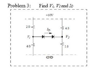
Transcribed Image Text:Problem 3:
Find V1, V2 and ID
2.0
V₁
4.0
+10V
GND
4.0
V₂
1.0
Expert Solution
This question has been solved!
Explore an expertly crafted, step-by-step solution for a thorough understanding of key concepts.
Step by stepSolved in 2 steps with 1 images

Knowledge Booster
Similar questions
- Need asap pls. Thanks.arrow_forwarda.Three conductances G1, G2, and G3 are in series. Write an expression for the equivalentconductance Geq=1/Req in terms of G1, G2, and G3. b. Repeat part (a) with the conductances in parallel.arrow_forward10 Write the expression for Vx in terms of V₁, V2 & the resistore. (6) from your answer in pant (a), let P1 = R₂= R3=1&₁ V₂ = 2V, Vi=10V&A. What is the numerical value of ? Viarrow_forward
- Derive please step by steparrow_forwardHelp me answer, I want to check my solution To get the contribution of the 75V source to iR, we first kill the 50mA source. What is the resulting equivalent resistance in series with the 75K resistor (in Kohms) To get the contribution of the 75V source to iR, we first kill the 50mA source. What is the resulting value of iR (in mA)? What is the nodal equation for Vx? What is the Thevanin voltage in (Volts) and Thevanin resistance in (Kohms)?arrow_forwardThe elements in the circuit shown have the following values: R1 = 1937.97 Q. R2 = 8792.15 Q. Rz R3 = 1441.86 0. It V1 = 8.1 V. 11 = 0.0072 A R. Vo Determine the following: a.) The Thevenin Resistance is, Rth (in ohms): b.) The Thevenin Voltage is, Vth (in volts): c.) The I, output voltage Vo (in volts): Assume R3 to be the load.arrow_forward
- Electrical Potential Energy In the image below, you have a before and after case. Initially q1 and q2 are close together. The charge q1 is being held stationary and is not allowed to move. But q2 is moved away from q1 and then held stationary. In the final image you can see where q2 has moved relative to q1. q1 q2 Initial +) Final + q1 q2 Look at the Initial set up and the Final set up. Is the Work done on q2 by the Electric Force positive or negative? Make sure to think about the signs of the charges and their relative distances.arrow_forwardB.. What is the load current for the circuit shown in the figure? Please choose one: a. 6.0 mA b. 3.0 mA C. 9.0 mA D. 7.5 mAarrow_forwardAfter solving for the total resistance, and the applied voltage being a given for the circuit, the next logical step is to .....? so that individual component voltages and currents can be found.arrow_forward
- Basic Electrical EngineeringDraw symbols of electrical components. Note: You may use both IEC and NEMA symbols. - Conductors crossing but not connected- Conductors crossing and connected - DC source other than battery- DC generator- AC voltage source- Ideal current source- Ideal Voltage Source- Current Controlled Current Source- Current Controlled Voltage Source- Voltage Controlled Current Source - Voltage Controlled Voltage Sourcearrow_forwardFor the given circuit, find the currents and (a) right after switch S is closed and (b) a long time after switch S has been closed. Let's now assume that the switch has been closed for a long time, and we again open the switch. (c) find the three currents right after the switch is open, and (d) find the potential drop across the resistor R2. (e) What would be values of all three currents a long time after switch S was opened second time? to R=120n R=30r L%3D3H %3Darrow_forwardUse image below for question ! arrow_forward
arrow_back_ios
SEE MORE QUESTIONS
arrow_forward_ios
Recommended textbooks for you
 Introductory Circuit Analysis (13th Edition)Electrical EngineeringISBN:9780133923605Author:Robert L. BoylestadPublisher:PEARSON
 Delmar's Standard Textbook Of ElectricityElectrical EngineeringISBN:9781337900348Author:Stephen L. HermanPublisher:Cengage Learning
 Programmable Logic ControllersElectrical EngineeringISBN:9780073373843Author:Frank D. PetruzellaPublisher:McGraw-Hill Education
 Fundamentals of Electric CircuitsElectrical EngineeringISBN:9780078028229Author:Charles K Alexander, Matthew SadikuPublisher:McGraw-Hill Education
 Electric Circuits. (11th Edition)Electrical EngineeringISBN:9780134746968Author:James W. Nilsson, Susan RiedelPublisher:PEARSON
 Engineering ElectromagneticsElectrical EngineeringISBN:9780078028151Author:Hayt, William H. (william Hart), Jr, BUCK, John A.Publisher:Mcgraw-hill Education,

Introductory Circuit Analysis (13th Edition)
Electrical Engineering
ISBN:9780133923605
Author:Robert L. Boylestad
Publisher:PEARSON

Delmar's Standard Textbook Of Electricity
Electrical Engineering
ISBN:9781337900348
Author:Stephen L. Herman
Publisher:Cengage Learning

Programmable Logic Controllers
Electrical Engineering
ISBN:9780073373843
Author:Frank D. Petruzella
Publisher:McGraw-Hill Education

Fundamentals of Electric Circuits
Electrical Engineering
ISBN:9780078028229
Author:Charles K Alexander, Matthew Sadiku
Publisher:McGraw-Hill Education

Electric Circuits. (11th Edition)
Electrical Engineering
ISBN:9780134746968
Author:James W. Nilsson, Susan Riedel
Publisher:PEARSON

Engineering Electromagnetics
Electrical Engineering
ISBN:9780078028151
Author:Hayt, William H. (william Hart), Jr, BUCK, John A.
Publisher:Mcgraw-hill Education,